Adjust shifter rods and cable wires
to dimensions shown in figure.Ad-
justmentcanbedonethroughaac-
cess hole on the RH side mud-
guard.
681
Model Code Page
42 Gearbox
13420
6000--8750
1. 1. 1995
1. 9. 1992
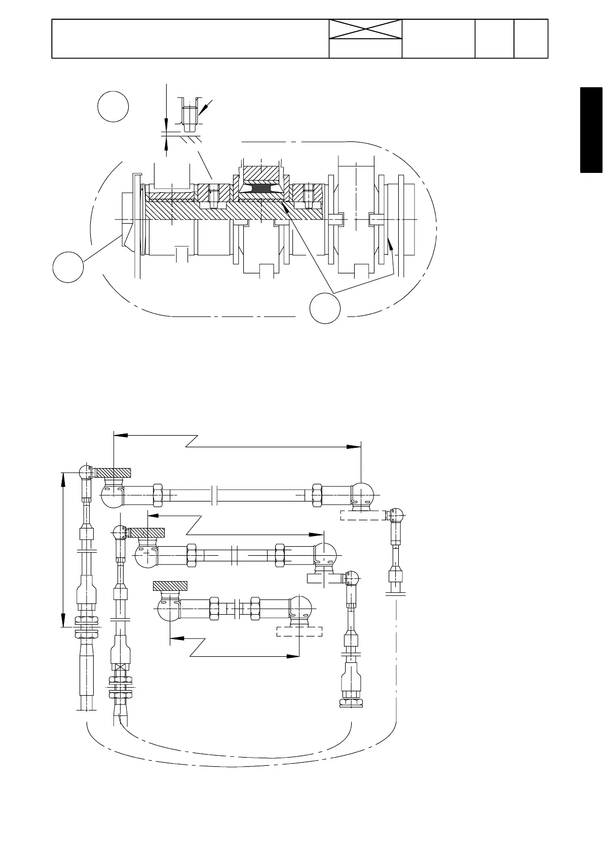
LOCTITE 542
0,3...0,7 mm
5
6
4
D
Figure 13. Gear lever support shaft (point D in figure 12)
Note! Rubber joints allow side movement for the speed and range gear levers
4. Force at the end of the reverse shuttle lever is adjusted to 10 ---20 Nm by tightening the shaft
5. Adjust distance to 0,3 ---0,7 mm by turning the pin
6. Universal grease
386---388 mm
446---448 mm
266---268 mm (---657167)
241 mm
M --- H
LL
2 --- 1
4 --- 3
R --- F
E
271---273 mm
Figure 14. Shifter rods and cable wires for inwards/outwards movement of the selector levers (point E in figure 12).
The gear lever must stand in the neutral position when adjusting measurement 241.