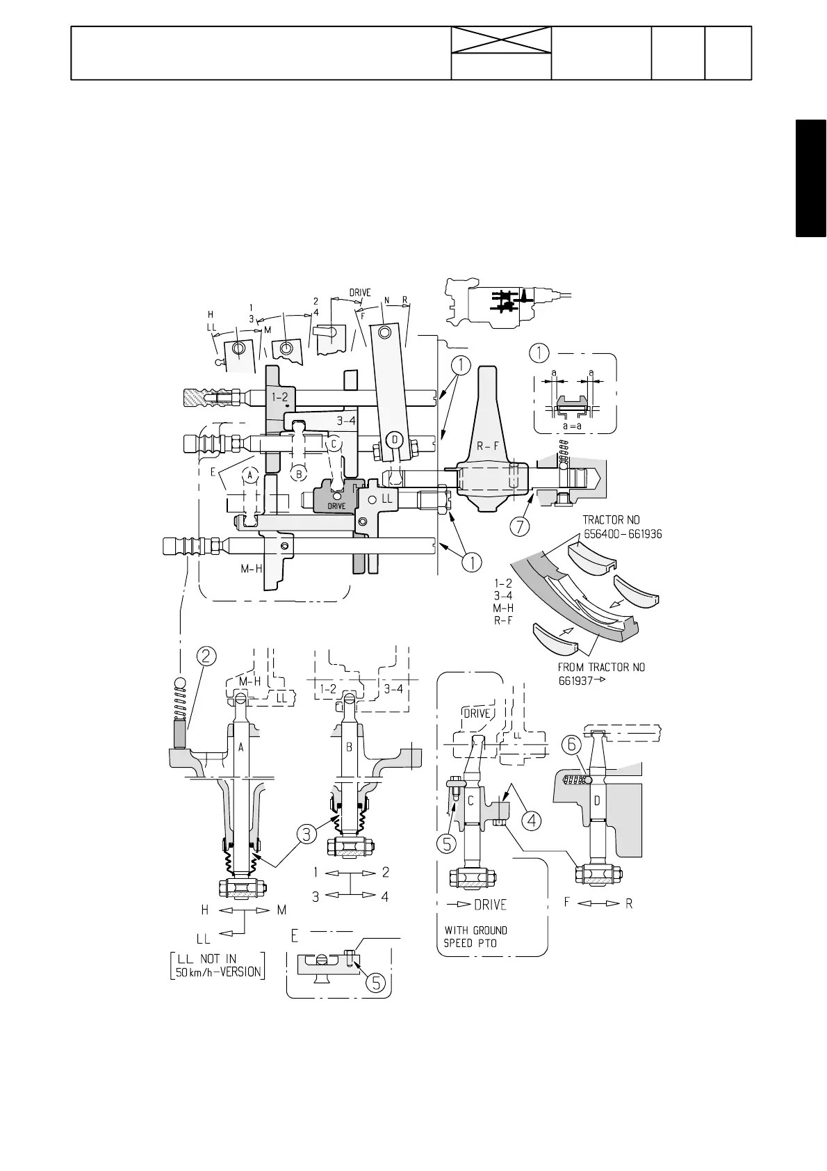
Figure 16. Selector forks and rails
2. Long pins into the two upper hole and short pin into the lowest hole
3. Universal grease
4. Hylosil sealing compound (UK 0067) between cover and gearbox
5. Loctite 242 (UK 0126).
683
Model Code Page
42 Gearbox
1. 1. 1995
15420
6000--8750
8. 11. 1990
Selector forks and selector fork rails
Each selector fork for gears M ---H, 1---2 and 3---4 are fitted on
their own rail. The forks are attached to the rails with a locking
pin. The selector lever round---shaped end engages with the
groove on the selector fork.
There is an adjusting piece at the rear end of the rails. There
are also locking balls and springs which engage with the ad-
justing piece grooves (3 pcs).
When the gears are in neutral, the grooves on forks M---H and
LL should be opposite eac h other. In the same way in neutral
position, the grooves on forks 1---2 and 3---4 should be oppo-
site each other. This must be noted when adjusting the forks.
The rail for fork LL (and for the ground speed PTO fork) is at-
tached to the gearbox housing with threads.
45---55 Nm
23---27 Nm