Servo hydraulics and lubrication
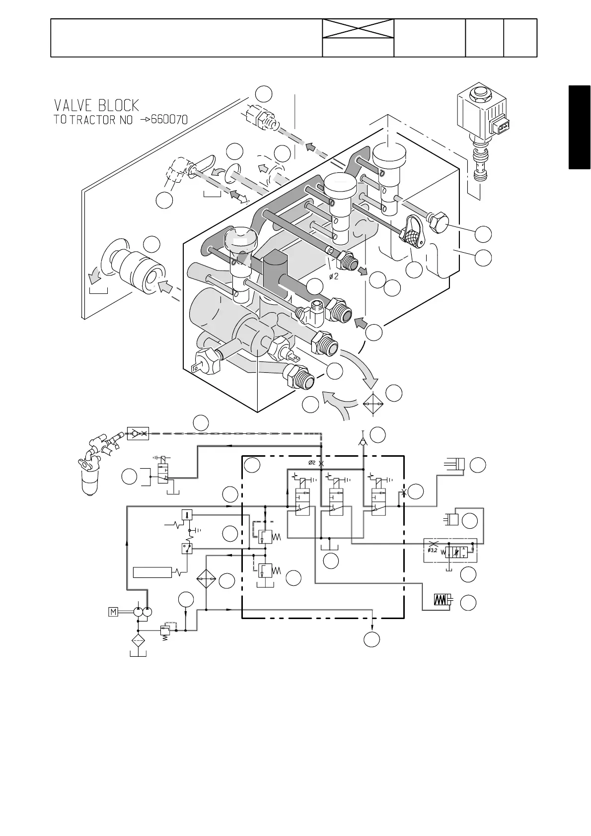
Figure 18. Servo valve block and hydraulics, earlier
valve block, ---660070.
1. Servo valve block
2. Oil supply from low pressure pump
3. Oil pressure and temperature sensors (S16, S17)
4. Safety valve for oil cooler (0,4 MPa)
5. Return oil to gearbox housing
6. Pressure test point (1,8 MPa)
7. Pressurised oil to diff. lock
8. Cushioning valve, PTO engagement
9. Pressurised oil to PTO clutch
10. Pressurised oil to 4WD clutch (external pipe)
11. To lubrication of transmission
12. Priority valve for steering (external pipe)
13.Powershift,quick---shiftgear(externalpipe)
14. Oil cooler
15. Return oil connection, working hydraulics
16. Diff. lock engaging pressure
Y1) Solenoid valve, diff. lock
Y2) Solenoid valve, PTO
Y3) Solenoid valve, 4WD
S16) Temperature sensor, gearbox temperature (90 ---96 ˚C)
S17) Oil pressure sensor, gearbox lubrication (20 ---50 kPa)
189
Model Code Page
42 Gearbox
15. 5. 1993
17420
6000--8100
1. 9. 2002
2
3
7
11
5
9
14
15
10
S16
S17
PTO
DIFF.L.
4
1
6
13
12
16
4WD
PTO CLUTC H
4WD
DELAY 5s
50 KPa
93±3˚C
0.4 MPa
1.8 MPa
DIFF.LOCK
TO LUBRICATION
PTO
POWER SHIFT
125 γm
0.2 MPa
Y3 Y2 Y1
3
4
14
S16
S17
8
12
6
7
9
10
11
5
Y4
15
DIFF.L.4WD
1
2
13
16