193
Model Code Page
42 Gearbox
19420
6000--8750
1. 1. 1994
1. 9. 2002
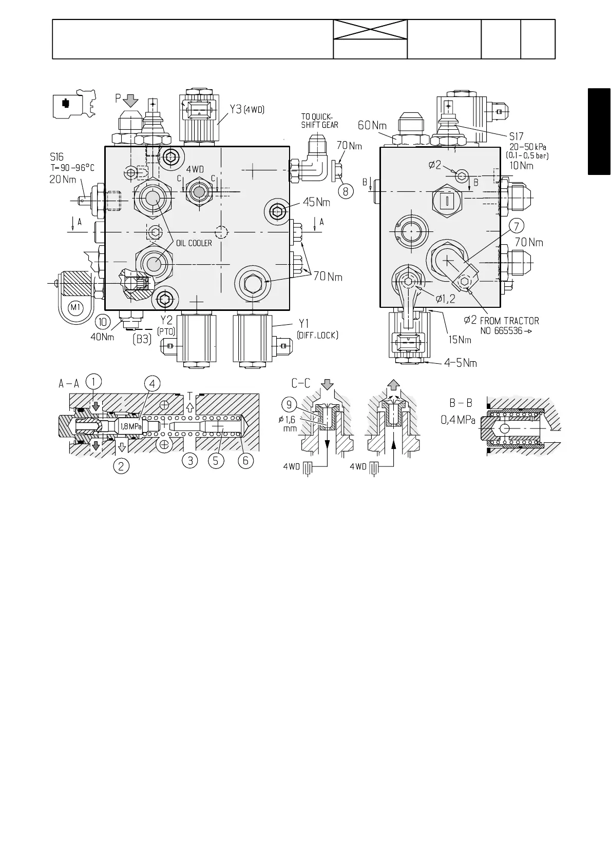
Later valve block 660071--- (on tractors without quick--- shift gear or with 2---step quick ---shift gear)
Picture 20B. Later servo valve bl ock on tractors without
quick ---shift gear or with 2 ---step quick---shift gear, 660071 ---.
Y1=Solenoid valve for diff. lock
Y2=Solenoid valve for PTO
Y3=Solenoid valve for 4WD
S16=transmission oil temperature se n sor (warning light)
S17=transmission oil pressure sensor (warning light)
P=Pressure oil supply from low pressure pump
M1. Pressure---test point (clutch pressures)
1) Pressure oil to the valve block (flows further to solenoid
valves).
2) To gearbox lubrication
3) Tank channel
4) Slide
5) Limiter
6) Fit shims, if needed
7) Connection with return line of the working hydraulics
8) Plugged when the quick ---shift gear has not been mounted.
9) Restriction/counter valve (Ø 1,6 mm restriction hole) pre-
vents the pressure drop in the DPS multi ---disc clutches, when
the 4WD has been disengaged (the multi ---disc clutch is then
pressurised), e.g. when braking. The valve has been mounted
from tractor no 668118 --->. The valve can be mounted after-
wards.
Left picture (4WD disengaged):
Oil flows through the restriction Ø 1,6 mm to the 4WD multi ---
disc clutch.
Right picture (4WD engaged):
Oil returns from the 4WD multi ---disc clutch without restricti on
(opening corresponds to a total hole of Ø 3,7 mm) to the tank.
10) Temperature sender unit for Agrodata --- display (optional
equipment).
Note! When the current is switched on to the solenoid valves,
the nut at the end of the valves becomes magnetic which can
be checked e.g. with a screwdriver. The 4WD clutch solenoid
valve is energized when the 4WD is disengaged.
This new servo valve block has the same functions as the ear-
lier valve block in figure 19. T h e b u i l d --- u p o f t h e p r e s s u r e ---
limiting valve is, however, different as well as the positions of
various components. In addition, this new valve has an in ---
build cus hioning valve for the PTO clutch (see section 46).
I f t h e t r a c t o r h a s 3 --- s t e p q u i c k --- s h i f t g e a r ( D e l t a P o w e r s h i f t ) ,
the tractor has this same valve block, but it has additionally
two extra solenoid valves and one valve spool and necessary
pipe connectors (see picture 20C on next page).
Note! With effect from tractor ser. no. 665536 the valve block
has been changed. The modified valve block can be fitted in
place of the earlier block. When fitting the latest valve block,
t h i c k e r ” O ” --- r i n g s ( KH 4070) must be fitted between the gear-
box and the valve block.
Important! If the valve block should be removed, push with
a large screwdriver the lubricating oil pipe (see picture 23
point 2 on page 420/22) towards the gearbox. Push the
screwdriver through the oil cooler lower pipe connector.
Otherwise the lubricating o il pipe lower end can loosen from
the distribution pipe.