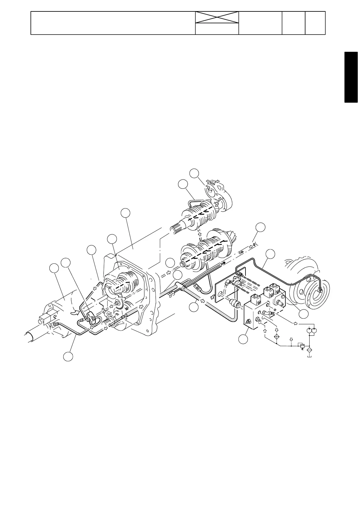
Figure 20. Lubricating system for power transmission on tractors
w i t h o u t q u i c k --- s h i f t g e a r o r w i t h 2 --- s t e p q u i c k --- s h i f t g e a r, ---660070.
1. Servo valve block ( ---660070)
2. Lubricating oil feed pipe
3. Distributor pipe
4. Lubricating oil to input shaft
5. Hydraulic pump dri ve mec h a nism
6. Distributor piece i n the front face of the reverse shuttle
7. Lubricating oil to bevel pinion shaft
8. Lubricating oil to PTO unit
9. Lubricating oil to quick--- shift gear
10. Lubricating oil to reverse shuttle
11. Gearbox housing
12. Quick---shift gear
13. Reverse shuttle
14. Pressurised oil to diff. lock
15. Solenoid valve for diff. lock
695
Model Code Page
42 Gearbox
15. 5. 1993
21420
6000--8750
Lubricating system
Gearbox input shaft and bevel pinion shaft have pressure lu-
brication. The low pressure circuit supplies oil for lubrication.
In addition, return oil from the hydraulic power lift is also deliv-
ered to the lubrication system (see hydraulicdiagram in figure
17).
Lubricating oil pressure---limiting valve (0,2 MPa) is fitted at
the rear end of the suction strainer housing on the gearbox.
Lubricating oil is delivered from the servo valve block via an
s---shaped pipe to the distributor pipe on the bottom of the
gearbox.
From the rear end of the distributor pipe has been drawn a
lubricat ing pipe to the rear end of the input shaft (and to the
hydraulic pump drive mechanism). Lubricating oilto the input
shaft lubricating points is channelled in thespacebetweenthe
input shaft and the pump drive shaft.
From the front end of the distributor pipe has been drawn a
pipe to the distributor piece in the front face of the reverse
shuttle housing. From the distributor piece lubricating oil is
conduc ted to the front end of the pinion shaft and via drillings
to the different lubricating points.
5
4
7
10
9
2
6
1
8
3
11
12
13
14
15
0,2 MPa