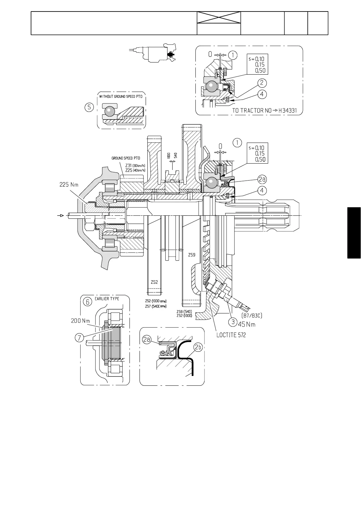
Figure 4. PTO shaft
1. Clearance is adjusted to zero with shims
2. Universal grease
2a. Cassette seal (H34332 ---). Fitting instruction, see page 462/8A.
2b. Protective cup for ca ssette seal
3. PTO rotation speed sensor (only E ---models)
4. Circlip
5. Unit without ground speed PTO
6. Earlier type locking flange at the PTO shaft front end
7. First activator Loctite 747 (reaction time 15 ---20 seconds) onto the
shaft and flange threads. Then locking fluid Loctite 270 and tighten
the flange to 200 Nm with special wrench ET 894 000.
821
Model Code Page
46. Power take ---off
1. 8. 1998
6000--8750 460 7
15. 5. 1993