835
Model Code Page
46. Power take ---off
8. 11. 1990
6000--8750 462 5
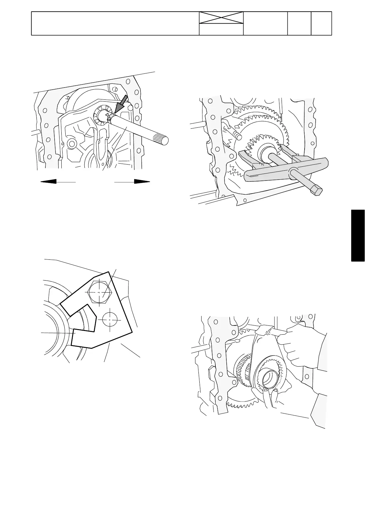
Adjusting clutch shaft bearing clearance
0,025---0,075
--- Remove the locking plate and turn the adjusting nut on the
shaft until there is no clearance in the clutch shaft taper roller
bearings
---Placeadialgaugestylusagainstahoseclippressedonthe
clutch shaft
--- Unscrew the adjusting nut so that the clearanc e of
0,025 ---0,075 mm is obtained for the bearings. Rotate the
shaft and press it to its extreme positionswhen measuring the
clearance.
21---25 Nm
--- Lock the adjusting nut with a locking plate and tighten its
fixing screw to 21---25 Nm. Apply Loctite 242 to threads.
Note! One step of the adjusting nut corresponds to about0,09
mm alteration on the clearance value. Note that the locking
plate can be fitted in two different way which doubles the
number of steps.
9. Fit the oil pipes and the oil distributor piece.
10. Fit the PTO unit (see instr. 1 G).
E. Removing selector fork and PTO shaft
gears
1. Remove the PTO unit (see instr. 1 A).
2. Carry out measures shown in instruction 1 B ; 2 --- 5 .
2492
3. a) Earlier version: Unscrew the locking flange at the front
end of the PTO shaft using ET 894000. Remove a spacer ring
and roller bearing and pull out the roller bearing inner race
with an extractor (see figure above).
b) Later version: Release the locking washer and unscrew
the locking bolt. Remove the flange and pull out the rol ler
bearing inner race as above.
Note! Tractors without ground speed PTO: Pull out the ball
bearing and remove the spacer sleeve and ring in front of the
gearwheel.
4. Remove the small ground speed PTO gearwheel (if fitted)
and the middle gearwheel for engine PTO 1000 r/min.
2493
5. Pull the selector fork and its rail out from the housing.
Change, if necessary, the inner selector lever which has a
round---shaped end. Fit a new fork onto the rail and secure it
with a locking pin.
Note! Fit the locking pin of the outer selector lever so that its
split side points forwards.
6.RemovethelargercirclipfortheoilsealretaineratthePTO
shaft rear end. Knock at the front end of thehollow shaft round