Installation
TITANUS
MICRO·SENS
®
122
06/13
8. For the cabling, route the connection cable(s) (max. 1.5 mm
2
) through
the prepared cable gland(s). The cable(s) are secured in position with
the cable tie mount(s) and cable ties.
9. Connect the network module as indicated in the following wiring diagram.
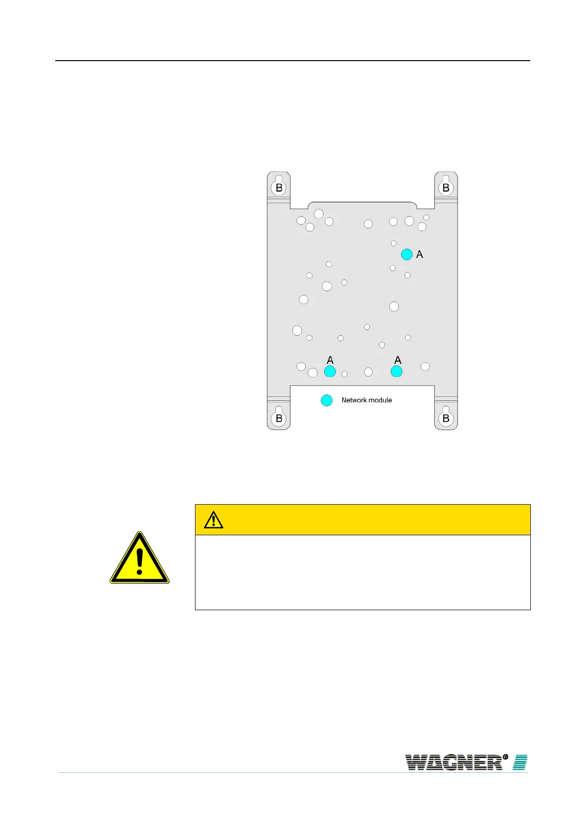
Figure 76: Fastening points on the network module installation plate
WARNING
All network cards are assigned the same IP address by the manufacturer. It
is necessary to ensure that the standard IP address (192.168.1.5) has not
been allocated in the network as this can otherwise cause network interfer-
ence.
10. Once successfully installed, close the cover by securely tightening the
four screws on the cover using a screwdriver.
11. Reconnect the voltage supply.

 Loading...
