Chapter 4 Inputs / Outputs ALPHA V40
Version 18.07.06
34
Warning Lights Connection (X6-ALARM LAMP)
There is no additional equipment required than the alarm
option itself to use this feature. If the warning lights are
connected to the 8-pin M12 Connection on controller rear
panel (refer to Fig. 4-1 on page 26), they work immediately.
The colours of lights with their accompanying meanings are
shown as the following:
Green - appears when the machine is in operating mode
(READY-Signal is true)
Yellow - appears when “Low Label” is detected
Fig.4-9: 3-Color Warning Lights
Red - appears when the machine is in error condition or the controller is in edit mode
(READY-Signal is false). Possible causes: Label End or Machine Fault
NOTE: Due to the limitation to a maximum value of 12W (500 mA) of the internal power
supply, it is necessary to use only alarm lamps with LED technique (Part-No. 22700995).
The 500 mA limit is intended as the sum of all loads on external connectors with 24 VDC
(alarm lamp, sensors, applicators...). In case of overload a thermal protection may
overheat and the CPU with the display switches off until the temperature decreases under
a safe value.
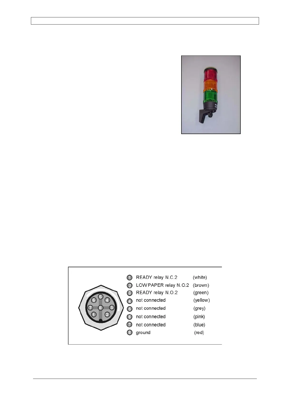
The ALARM LAMP uses an 8-pin M12 female socket on which some of the signals already
available on the RELAY OUTPUTS socket are duplicated (follows on Page 36).
See Figure 4-10 for the pinout.
Fig. 4-10: Alarm Connector