ENGINE
M6060, M7060, WSM
1-M13
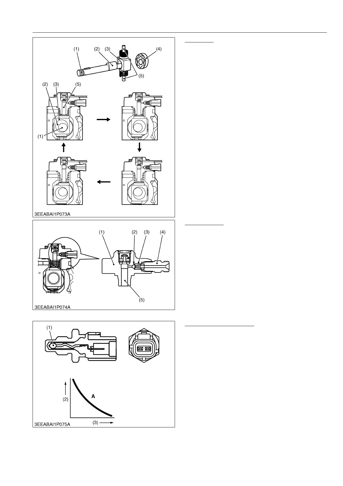
Pump Unit
The pump unit works to increase the pressure of fuel
received from the SCV and consists of a drive shaft (1),
ring cam (3) and two plungers (5). A ring cam (3) is
mounted on the outside of the eccentric cam (2), which
is on the same axle as the drive shaft; the plungers are
arranged symmetrically vertically on the ring cam.
When the drive shaft rotates, the eccentric cam
rotates eccentrically and the ring cam (3) is driven up
and down by it, which operates the two plungers (5)
through their cycles.
9Y1210828ENM0020US0
Delivery Valve
The delivery valve is integrated with the element (1)
and consists of a check ball (2), spring (3) and holder (4).
When the pressure on the plunger side (5)
equals/exceeds the pressure on the rail side, the check
ball opens and discharges fuel. As soon as the fuel
pressure feed is complete, the check ball is pressed
back by the spring and when it touches the seat of the
element, it cuts off the rail side from the plunger side,
thus preventing any backflow of fuel.
9Y1210828ENM0021US0
Fuel Temperature Sensor
The fuel temperature sensor is mounted on the fuel
intake side and detects the temperature of the fuel using
the characteristic of the thermistor (1), whose electrical
conductivity varies with temperature.
Please note that the fuel temperature sensor is not
treated as a part, so replacing it requires replacement of
the supply pump.
9Y1210828ENM0022US0
(1) Drive Shaft
(2) Eccentric Cam
(3) Ring Cam
(4) Feed Pump
(5) Plunger
(1) Element
(2) Check Ball
(3) Spring
(4) Holder
(5) Plunger
(1) Thermistor
(2) Resistance
(3) Temperature
A: Thermistor Temperature
Change Curve