ELECTRICAL SYSTEM
M6060, M7060, WSM
8-S44
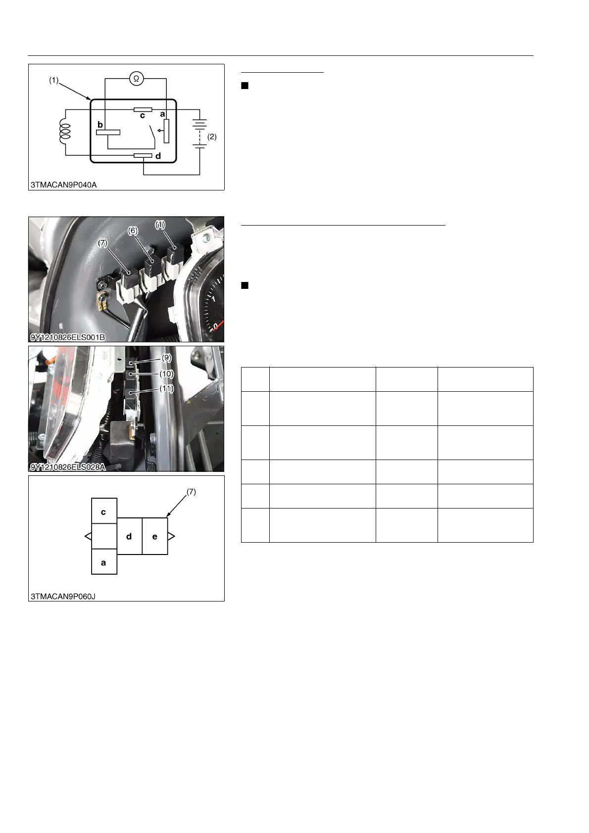
Functional Check
• The relays described here are used same ones so that
these are interchangeable.
1. Apply battery voltage across the terminals c and d, and check
for continuity across the terminals a and b.
2. If continuity is not established across the terminals a and b,
replace it.
9Y1210828ELS0080US0
(2) Relays
Checking Connector Voltage (ROPS Model)
1. Measure the voltage with a voltmeter across the battery terminal
and chassis as table below.
2. If the voltage differs from the battery voltage, the wiring harness
or fuse is faulty.
• Be sure to use the 5 terminal type relay for the engine stop
relay (1).
• Other relays can use both 4 terminal type relay and 5
terminal relay.
• The color of the relay are black, both 4 terminal type relay
and 5 terminal type relay.
9Y1210828ELS0081US0
(1) Connector (Relay) (2) Battery
(1)
Engine stop relay (main
switch at ON position)
Terminal c –
Chassis
Approx. battery voltage
(2)
PTO safety relay (main
switch at ON position and
PTO lever OFF position)
Terminal c –
Chassis
Approx. battery voltage
(3)
Work light relay (front)
(main switch at OFF
position)
Terminal e –
Chassis
Approx. battery voltage
(4)
Key stop relay (main switch
at OFF position)
Terminal e –
Chassis
Approx. battery voltage
(5)
Head light relay (low) (main
switch at OFF position)
Terminal d –
Chassis
Approx. battery voltage
(6)
Head light relay (high)
(main switch at OFF
position)
Terminal d –
Chassis
Approx. battery voltage
(1) Engine Stop Relay
(Green: 5 Terminals Type)
(2) PTO Safety Relay
(3) Work Light Relay (Front)
(4) Key Stop Relay
(5) Head Light Relay (Low)
(6) Head Light Relay (High)
(7) Connector (Wire Harness)