ELECTRICAL SYSTEM
M6060, M7060, WSM
8-S48
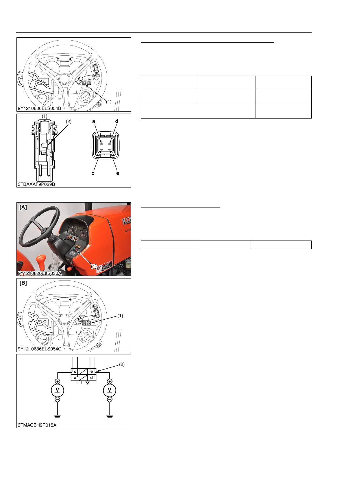
Checking Horn Switch Continuity (CABIN Model)
1. Measure the resistance with ohmmeter across the terminal a
and terminal c, and across the terminal d and terminal e.
2. If the measurement is not following below, the horn switch or the
bulb are faulty.
9Y1210828ELS0088US0
(3) Hazard Switch
Checking Connector Voltage
1. Connect the battery negative code, then measure the voltage
with a voltmeter across the each terminal c/e and chassis.
2. If the voltage differ from the battery voltage, the wiring harness
is faulty.
9Y1210828ELS0089US0
Resistance
(Switch at OFF)
Ter min al a – Terminal c Infinity
Resistance
(Switch at ON)
Ter min al a – Terminal c 0 Ω
Resistance
(Bulb)
Ter min al d – Terminal e Approx. 13 Ω
(1) Horn Switch (2) Bulb
Voltage Terminal c/e – Chassis Approx. battery voltage
(1) Hazard Switch
(2) 6P Connector (Wire Harness Side)
[A] ROPS Model
[B] CABIN Model