ENGINE
M6060, M7060, WSM
1-S56
[4] SERVICING
(1) Cylinder Head and Valves
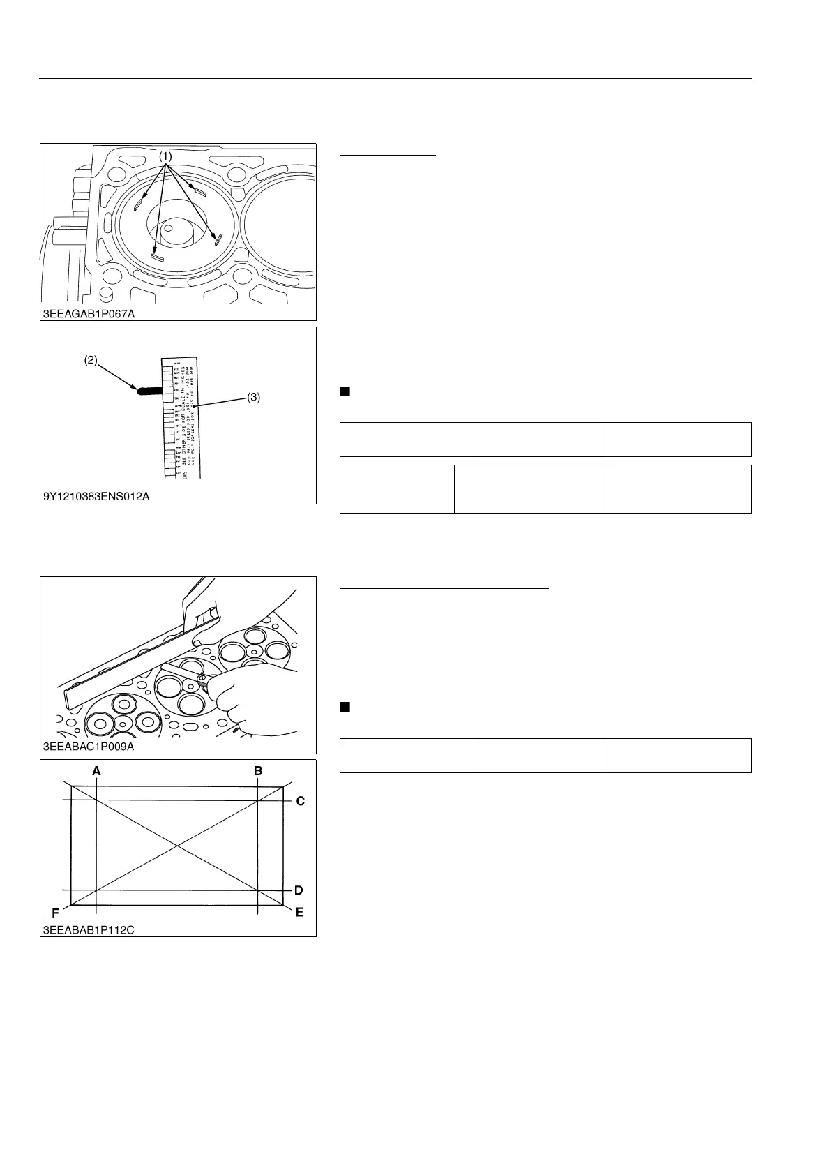
Top Clearance
1. Remove the cylinder head.
2. With the piston at TDC, use grease to affix three or four
plastigauges (1) of a diameter 1.5 mm (0.059 in.) x 5.0 to
7.0 mm (0.20 to 0.27 in.) long to the crown of the piston; keep
the gauges away from the intake valve and combustion
chamber fittings.
3. Take the piston to an intermediate position, install the cylinder
head and tighten the head bolts to the specified torque.
4. Turn the crankshaft so the piston goes through TDC.
5. Remove the cylinder head and compare the width of the
crushed plastigauges (2) with the scale (3).
6. If they are out of spec, check the oil clearance of the crank pin,
journal and piston pins.
• Top clearance = Width of the crushed plastigauge (2)
9Y1210828ENS0077US0
Cylinder Head Surface Flatness
1. Clean the cylinder head surface.
2. Place a straightedge on the cylinder head's four sides "A", "B",
"C" and "D" and two diagonal "E" and "F" as shown in the
figure. Measure the clearance with a feeler gauge.
3. If the measurement is more than the allowable limit, make it
straight with a surface grinder.
• Examine the valve recessing after you correct.
9Y1210828ENS0078US0
Top clearance Factory Specification
0.60 to 0.80 mm
0.024 to 0.031 in.
Tightening torque
Cylinder head mounting
screw
187 to 196 N·m
19.0 to 20.0 kgf·m
138 to 144 lbf·ft
(1) Plastigauge
(2) Crushed Plastigauge
(3) Scale
Cylinder head surface
flatness
Allowable limit
0.05 mm
0.002 in.