ELECTRICAL SYSTEM
M6060, M7060, WSM
8-S14
(4) Connector
Checking Connector
1. When inspect the circuit line, check the related connectors.
2. Disconnect the connectors and check their terminals for
contamination and deformation.
3. Check to see that cable does not broken or terminals are not
shelled off.
4. If any damaged parts are found, repair or replace them.
• Connect connector surely after checked.
9Y1210828ELS0015US0
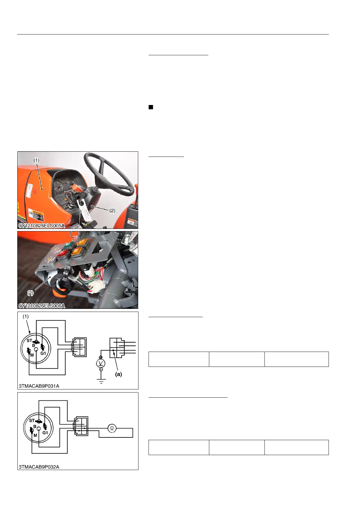
[2] MAIN SWITCH
(1) ROPS Model
Main Switch
1. Remove the panel cover (1) and steering post cover (2).
2. Disconnect the 4P connector for main switch (3).
3. Remove the main switch (3).
9Y1210828ELS0016US0
Connector Voltage
1. Measure the voltage with a voltmeter across the connector
terminal B and chassis.
2. If the voltage differs from the battery voltage (11 to 14 V), the
wiring harness is faulty.
9Y1210828ELS0017US0
Main Switch at ON Position
1. Turn the main switch to ON position.
2. Measure the resistance with an ohmmeter across the terminal
B and the terminal M.
3. If 0 ohm is not indicated, the B – M contacts of the main switch
are faulty.
9Y1210828ELS0018US0
(1) Panel Cover
(2) Steering Post Cover
(3) Main Switch
Voltage
Connector terminal B
– Chassis
Approx. battery voltage
(1) Main Switch (a) From Battery Positive Terminal
Resistance
Ter min al B –
Ter min al M
0 Ω