HYDRAULIC SYSTEM
M6060, M7060, WSM
7-S29
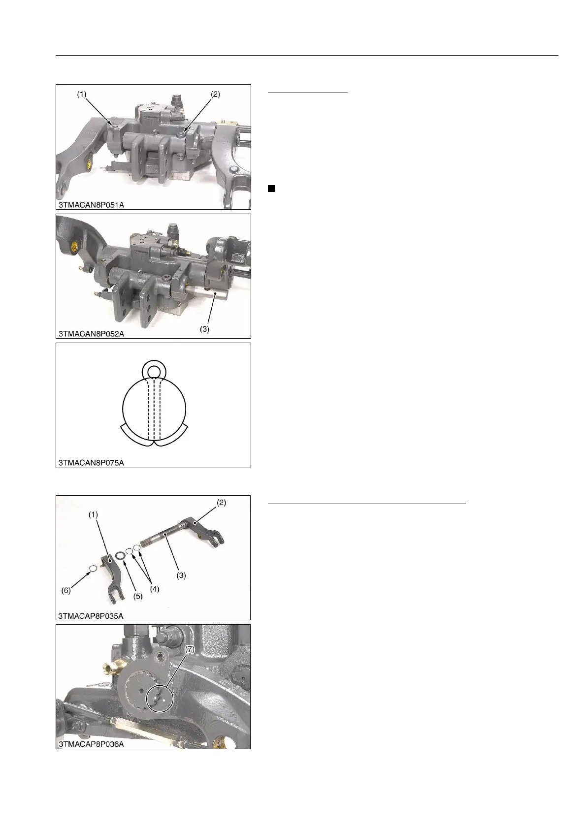
[8] TOP LINK BRACKET
Top Link Bracket
1. Remove the position and draft feedback rod.
2. Remove the cotter pin and the clevis pins (1) and (2).
3. Draw out the torsion bar (3).
(When reassembling)
• Apply grease to the torsion bar bushing.
• Replace the cotter pin with new one, and assemble as shown
figure.
• After assembling the top link bracket, be sure to adjust the
position and draft feedback levers.
• Grease up to the grease fittings.
9Y1210828HYS0035US0
[9] LIFT ARM AND LIFT ARM SHAFT
Disassembling Lift Arm and Lift Arm Shaft
1. Remove the external circlip (6).
2. Remove the lift arm R.H. (2).
3. Draw out the lift arm shaft (3) and lift arm L.H. (1) as a unit.
4. Remove the collar (5) and O-rings (4).
(When reassembling)
• Align the alignment marks (7) of the lift arm shaft and lift arms.
• Apply grease to the right and left bushings of lift arm support and
O-rings.
• Be careful not to damage the O-rings.
9Y1210828HYS0036US0
(1) Clevis Pin
(2) Clevis Pin
(3) Torsion Bar
(1) Lift Arm L.H.
(2) Lift Arm R.H.
(3) Lift Arm Shaft
(4) O-ring
(5) Collar
(6) External Circlip
(7) Alignment Mark