ENGINE
M6060, M7060, WSM
1-S55
(Continued)
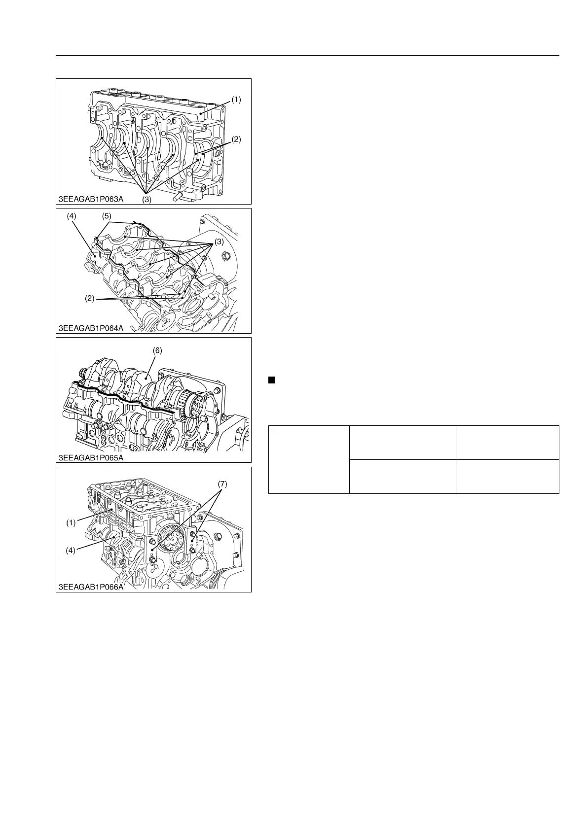
(When reassembling)
• Make sure the crankcase 1 (4) and 2 (1) are clean.
• Reassemble the crankshaft bearing (3) into crankcase 1 (4) and
2 (1).
• Reassemble the thrust bearing (2), with the oil groove facing
outside, into both flywheel housing edge journal side of the
crankcase 1 (4) and 2 (1).
• Apply oil to the thrust bearing and set the crankshaft (6).
• Apply liquid gasket (Three Bond 1217H or equivalent) (5) to the
crankcase 1 as shown in the figure.
• Make sure that the liquid gasket coating surface is free of water,
dust and oil in order to keep sealing effect.
• Carefully apply the adhesive evenly.
• Match the crankcase 1 (4) and 2 (1), referring to the flywheel
housing's contoured face.
• Tighten the crankcase 2 mounting screws (A to J) and the
crankcase 2 flange screws (K to Z) loosely after applying engine
oil.
• Tighten up the jig (7) to the specified torque same as the
flywheel housing screw. (See page G-59.) This helps to
minimize the level difference between the crankcase 1 (4) and
the crankcase 2 (1) (at the flywheel side). Possible gap must be
0.05 mm (0.002 in.) or smaller.
• Tighten the crankcase 2 mounting screw and the crankcase 2
flange screw in the order of A to Z. (Refer to previous page.)
• When mounting the adhesive-applied parts, be careful to fit
them to the mating parts.
• Assemble the adhesive-applied parts within ten minutes.
9Y1210828ENS0076US0
Tightening torque
Crankcase 2 mounting
screw (A to J)
138 to 147 N·m
14.0 to 15.0 kgf·m
102 to 108 lbf·ft
Crankcase 2 flange screw
(K to Z)
59 to 63 N·m
6.0 to 6.5 kgf·m
44 to 47 lbf·ft
(1) Crankcase 2
(2) Thrust Bearing
(3) Crankshaft Bearing
(4) Crankcase 1
(5) Liquid Gasket
(6) Crankshaft
(7) Jig