ELECTRICAL SYSTEM
M6060, M7060, WSM
8-S45
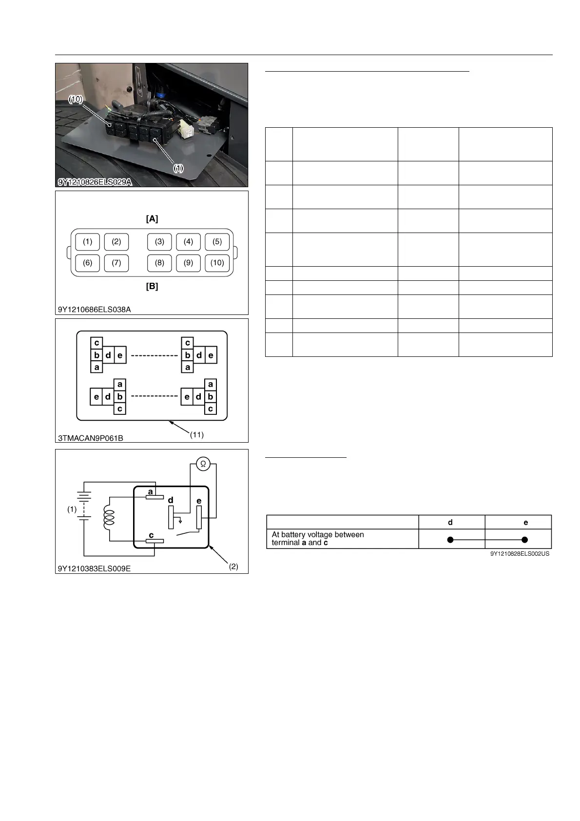
Checking Connector Voltage (CABIN Model)
1. Measure the voltage with a voltmeter across the battery terminal
and chassis as table below.
2. If the voltage differs from the battery voltage, the wiring harness
or fuse is faulty.
9Y1210828ELS0082US0
Functional Check
1. Apply battery voltage across the terminals a and c, and check
for continuity across the terminals d and e.
2. If continuity is not established across terminals d and e, replace
it.
9Y1210828ELS0083US0
(1)
PTO safety relay (main
switch at ON position and
PTO lever OFF position)
Terminal c –
Chassis
Approx. battery voltage
(2) Front light relay
Terminal e –
Chassis
Approx. battery voltage
(3)
Air conditioner blower high
relay
Terminal c –
Chassis
Approx. battery voltage
(4)
Working Light Relay (main
switch at OFF position)
Terminal e –
Chassis
Approx. battery voltage
(5)
Air conditioner blower relay
(main switch at ACC
position)
Terminal d –
Chassis
Approx. battery voltage
(6) PTO relay Approx. battery voltage
(7) Neutral relay Approx. battery voltage
(8) Front motor relay
Terminal c –
Chassis
Approx. battery voltage
(9) Side lamp relay Approx. battery voltage
(10)
Air compressor relay (main
switch at OFF position)
Terminal d –
Chassis
Approx. battery voltage
(1) PTO Safety Relay
(2) Front Light Relay
(3) Air Conditioner Blower High Relay
(4) Working Light Relay
(5) Air Conditioner Blower Relay
(6) PTO Relay
(7) Neutral Relay
(8) Front Motor Relay
(9) Side Lamp Relay
(10) Air Compressor Relay
(11) Connector Box
[A] Plate Side
[B] Blower Side
(1) Battery (2) Connector (Relay)