ENGINE
M6060, M7060, WSM
1-S12
Valve Clearance
• You must examine and adjust the valve clearance when the
engine is cold.
1. Remove the injection pipes, glow lead, glow plugs and the
cylinder head cover.
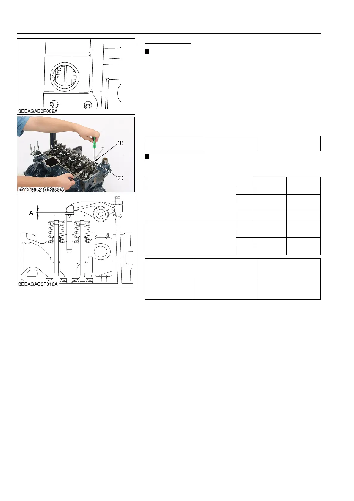
2. Align the "1TC" mark line on the flywheel and projection on the
housing. Make sure that the No.1 piston (front cover side)
comes to the compression or overlap top dead center.
3. Examine the subsequent valve clearance at the mark "1TC"
with a feeler gauge. If the clearance is out of the factory
specifications, adjust with the adjusting screw (1) and tighten
the lock nut (2) of the adjusting screw.
• After you adjust the valve clearance, tighten the lock nut (2)
of the adjusting screw.
9Y1210828ENS0005US0
Valve clearance (A) Factory specification
0.13 to 0.17 mm
0.0052 to 0.0066 in.
Adjustable Cylinder Location of Piston IN. EX.
When No. 1 piston is at compression top
dead center
1st
2nd
3rd
4th
When No. 1 piston is at overlap position
1st
2nd
3rd
4th
Tightening torque
Cylinder head cover screw
9.81 to 11.2 N·m
1.00 to 1.15 kgf·m
7.24 to 8.31 lbf·ft
Injection pipe retaining nut
30 to 40 N·m
3.1 to 4.0 kgf·m
23 to 29 lbf·ft
(1) Adjusting Screw
(2) Lock Nut
A : Valve Clearance