ENGINE
M6060, M7060, WSM
1-S65
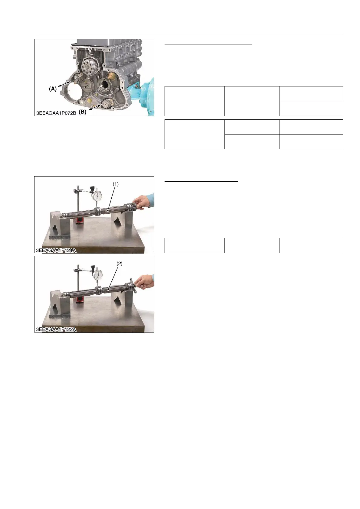
Balancer Shaft Side Clearance
1. Set a dial indicator with tip on the balancer shaft.
2. Measure the side clearance by moving the balancer shaft to the
front and rear.
3. If the measurement exceeds the allowable limit, replace the
balancer shaft.
9Y1210828ENS0101US0
Balancer Shaft Alignment
1. Support the balancer shaft with V blocks on the surface plate
and set a dial indicator with its tip on the intermediate journal at
high angle.
2. Rotate the balancer shaft on the V block and get the
misalignment (half of the measurement value).
3. If the misalignment exceeds the allowable limit, replace the
balancer shaft.
9Y1210828ENS0102US0
Side clearance of
balancer shaft 1
Factory specification
0.070 to 0.220 mm
0.0028 to 0.0087 in.
Allowable limit
0.3 mm
0.0118 in.
Side clearance of
balancer shaft 2
Factory specification
0.070 to 0.320 mm
0.0028 to 0.0126 in.
Allowable limit
0.3 mm
0.0118 in.
(A) Side Clearance of Balancer Shaft
2
(B) Side Clearance of Balancer Shaft
1
Balancer shaft 1, 2
alignment
Allowable limit
0.02 mm
0.0008 in.
(1) Balancer Shaft 1 (2) Balancer Shaft 2



 To Next Page