ENGINE
M6060, M7060, WSM
1-S69
Connecting Rod Alignment
• Make sure that the oil clearance of the small end bushing is
less than the allowable limit.
1. Remove the piston pin from the piston.
2. Install the piston pin into the connecting rod.
3. Install the connecting rod on the alignment tool of the
connecting rod.
4. Put a gauge on the piston pin, and move it against the face
plate.
5. If the gauge does not touch fully against the face plate, measure
the space between the gauge pin and face plate.
6. If the measurement is more than the allowable limit, replace the
connecting rod.
9Y1210828ENS0108US0
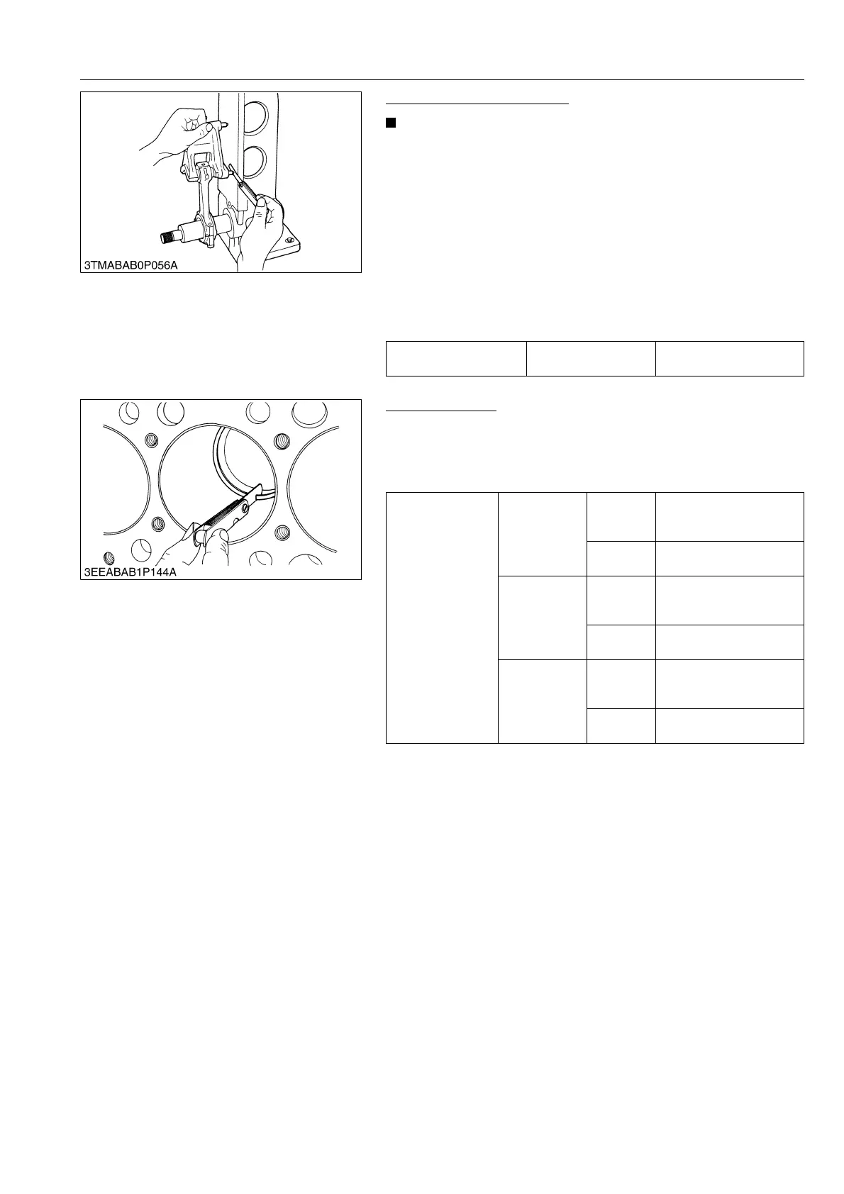
Piston Ring Gap
1. Put the piston ring into the lower part of the liner (the least worn
out part) with the piston.
2. Measure the ring gap with a feeler gauge.
3. If the ring gap is more than the allowable limit, replace the ring.
9Y1210828ENS0109US0
Connecting rod
alignment
Allowable limit
0.05 mm
0.002 in.
Piston ring gap
Top ring
Factory
specifica-
tion
0.25 to 0.40 mm
0.0099 to 0.015 in.
Allowable
limit
1.25 mm
0.0492 in.
Second ring
Factory
specifica-
tion
0.30 to 0.45 mm
0.012 to 0.017 in.
Allowable
limit
1.25 mm
0.0492 in.
Oil ring
Factory
specifica-
tion
0.25 to 0.45 mm
0.0099 to 0.017 in.
Allowable
limit
1.25 mm
0.0492 in.