STEERING
M6060, M7060, WSM
6-S11
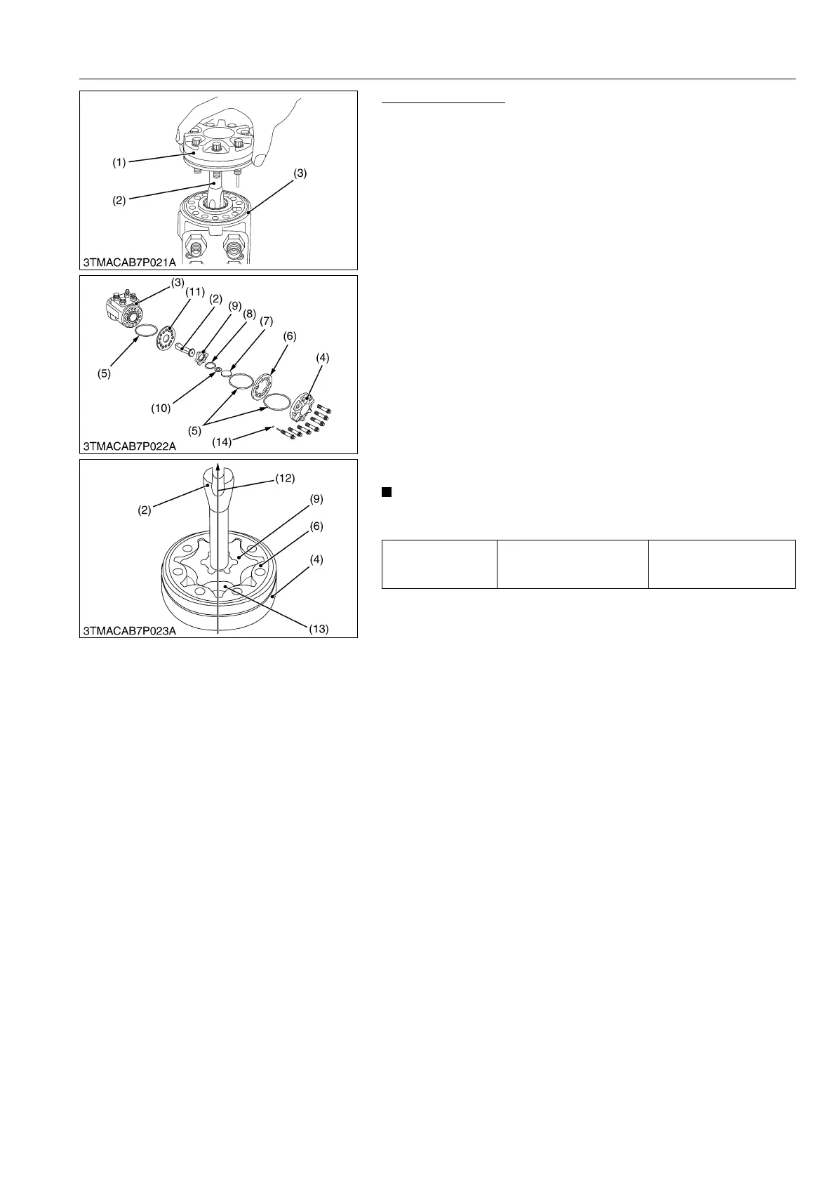
Removing Gerotor
1. Secure the housing (3) in a vise and remove seven gerotor
mounting screws and gerotor assembly (1).
2. Remove the distributor plate (11) and driven shaft (2).
3. Remove the rotor (9), O-ring (5) between the distributor plate
and stator (6).
4. Remove the spacer ring (10) and spacer (7).
5. Remove the O-ring (8) from the rotor (9).
(When reassembling)
1. Fit an O-ring into the groove of the end cap (4), and insert 2 or
3 bolts.
2. Fit an O-ring into the groove of the stator (6), and put it on the
end cap, with the O-ring upward.
3. Apply clean transmission fluid (specified fluid) to the rotor (9), fit
an O-ring (8) into the groove of the rotor and put the spacer on
it. Keeping the spacer on the rotor, fit it into the stator (6) with
the spline bevelled side upward.
4. After putting the spacer into the rotor (9), insert the splines of
driven shaft (2) into the rotor (9), aligning the direction of drive
shaft pin groove (12) with the rotor tooth bottom (13).
5. Fit an O-ring into the groove of the housing (3).
Fit the pin groove of the driven shaft (2) to the dowel pin inside
the housing.
• Be sure to align the direction of the drive shaft pin groove
(12) with the rotor tooth bottom (13).
9Y1210828STS0015US0
Tightening torque
Gerotor assembly
mounting screw (5/16')
25.5 to 28.4 N·m
2.6 to 2.9 kgf·m
18.8 to 21.0 lbf·ft
(1) Gerotor Assembly
(2) Driven Shaft
(3) Housing
(4) End Cap
(5) O-ring
(6) Stator
(7) Spacer
(8) O-ring
(9) Rotor
(10) Spacer Ring
(11) Distributor Plate
(12) Direction Pin Groove
(13) Rotor Tooth Bottom
(14) Ball