ELECTRICAL SYSTEM
M6060, M7060, WSM
8-S57
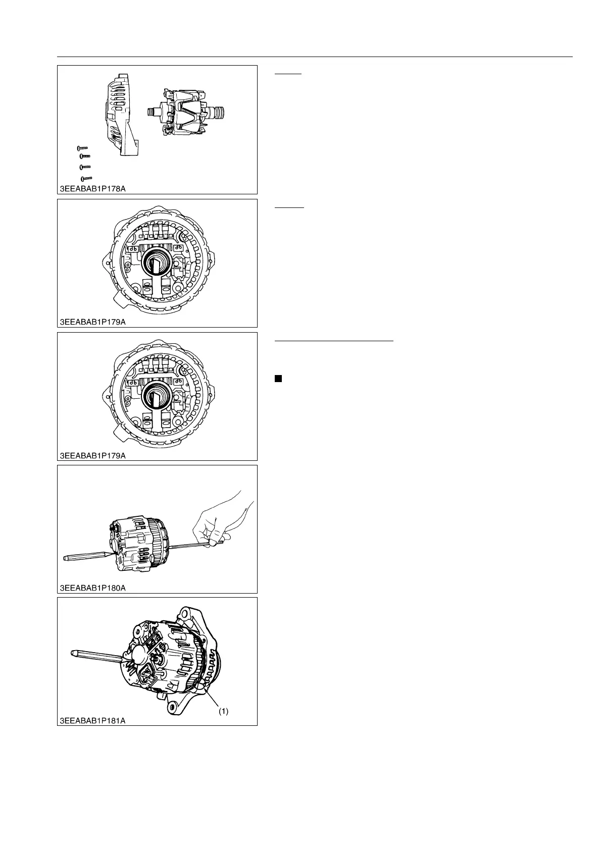
Rotor
1. Remove the 4 screws and remove the bearing retainer.
2. Temporarily install the nut on the pulley screw, and remove the
rotor.
9Y1210828ELS0104US0
Brush
1. When the rotor is removed, the 2 brushes are found to stretch
out of the shaft hole.
9Y1210828ELS0105US0
Reassembling the Brush
1. Fit the brush with its sliding face in the clockwise direction when
viewed from front.
• Be sure to keep the 2 brushes deep in the brush holder.
Otherwise the rotor and the rear section can not be fitted
into position.
• Use a 4 mm hex. wrench to push the brushes into place.
• Using a pin-pointed (2 mm) punch, keep the brushes from
popping out.
2. Match the tally line of the front section with that of the rear
section.
3. Tighten the 4 screws, and draw out the pin-pointed punch out of
the brush holder.
9Y1210828ELS0106US0
(1) Marking