CABIN
M6060, M7060, WSM
9-S26
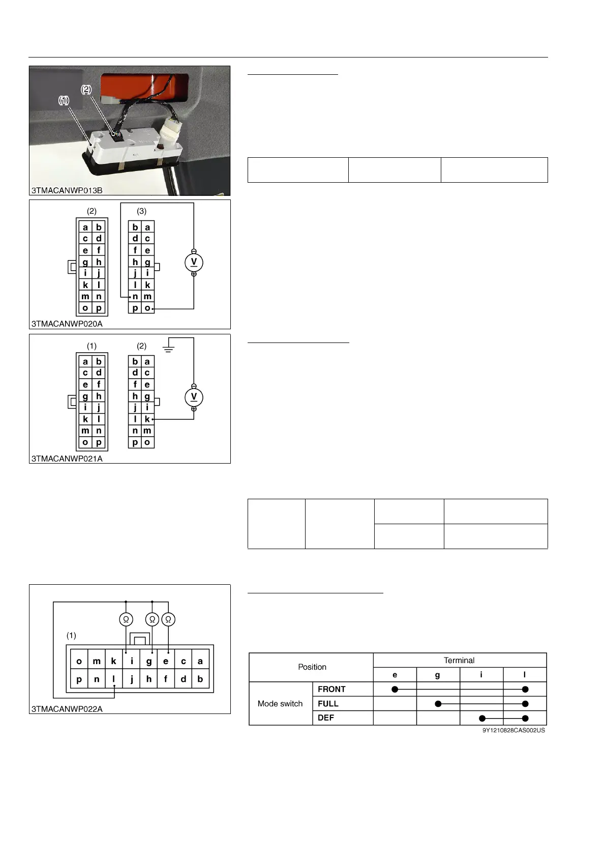
Connector Voltage
1. Disconnect the 16P connector (2) from control panel switch.
2. Turn the main switch to "ON" position.
3. Measure the voltage with a voltmeter across the terminal o and
terminal n.
4. If the voltage differs from the battery voltage, the wiring harness,
A/C relay or fuse is faulty.
9Y1210828CAS0041US0
A/C Switch Checking
1. Measure the voltage with a voltmeter across the terminal k and
chassis.
2. Turn the main switch to "ON" position.
3. Turn the blower switch to "ON" position.
4. Press the air conditioner switch to set it to "OFF" position
(indicator: OFF), and then measure a voltage using a circuit
tester.
5. Press the air conditioner switch to set it at "ON" position
(indicator: ON), and then measure a voltage using a circuit
tester.
6. If a measured voltage does not comply with the values in the
table below, the control panel, wiring harness or fuse is faulty.
9Y1210828CAS0042US0
Mode Control Dial Checking
1. Disconnect the 16P connector from control panel switch.
2. Check the continuity through the switch with an ohmmeter.
3. If the continuity specified below is not indicated, the switch is
faulty.
9Y1210828CAS0043US0
Voltage
Ter min al n –
Ter min al o
Approx. battery voltage
(1) Control Panel
(2) 16P Connector (Switch Side)
(3) 16P Connector (Wire Harness Side)
Voltage
Ter min al k –
Chassis
A/C switch at
ON
Approx. battery voltage
A/C switch at
OFF
Approx. 1 V
(1) 16P Connector (Switch Side) (2) 16P Connector (Wire Harness Side)
(1) 16P Connector (Switch Side)