6. Remove the Web Oiler Assembly (REP 10.7).
NOTE: In the following steps, "Left" and "Right"
describe machine locations as observed when you
are facing the Xerographic Module at the left side of
the Printer.
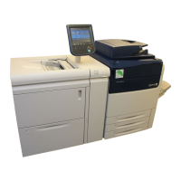
7. (Figure 2): Install the Handles onto the Left and
Right Side of the Xerographic Module.
1
Attach the Handle
into the slot
R3002K
. . Secure the
fastener
Figure 2. Installing the Handles (Right
Side)
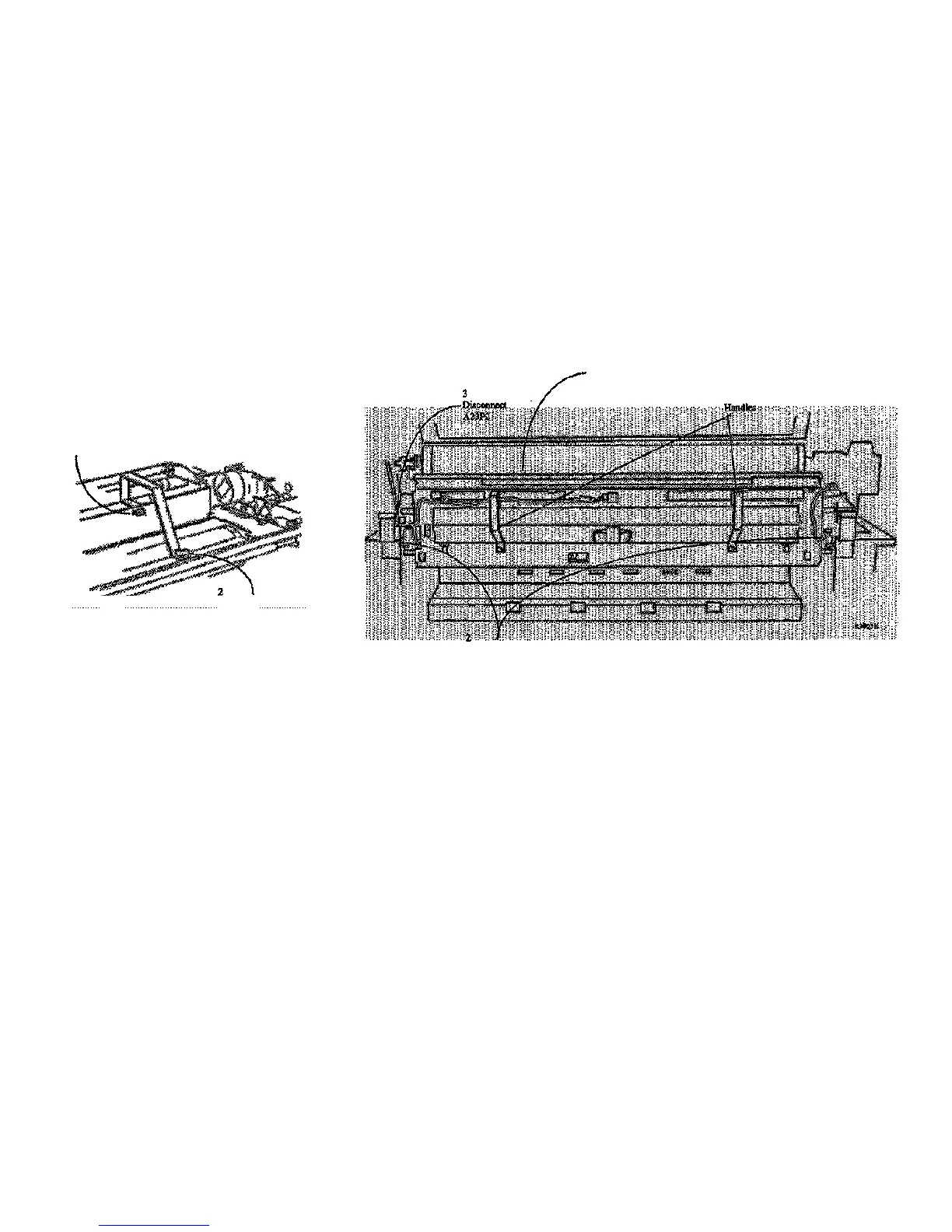
NOTE: The latches that secure the Xerographic
Module to the Printer Frame are spring-loaded and
will automatically engage the holes. The latches have
a 1/4 turn lockout feature that may be used to prevent
actuation during reinstallation of the Xerographic
Module. When performing the following step, ensure
that the spring-loaded feature is active.
8. (Figure 3): Using the handles, rotate the
Xerographic Module 90 degrees so that the
latches lock into the holes in the frame.
. Rotate the Xerographic
Module 90 degrees
Ensure that the Xerographic
Module is latched to the Frame
Figure 3. Latching the Xerographic Module at the Service Position
REP 9.1
1/98
4-44
8830

 Loading...