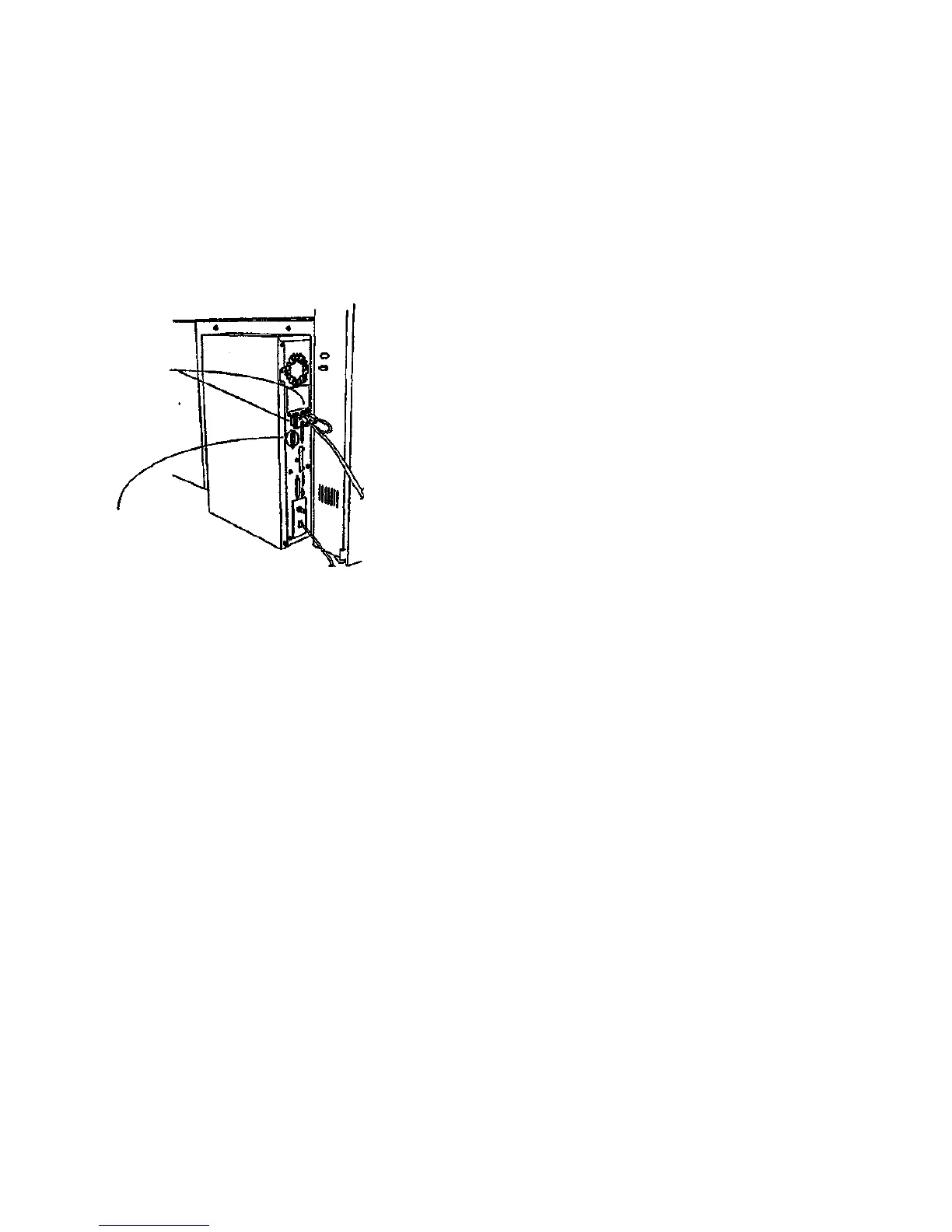
Ensure 6830 DDS
Control Panel Cable
is connected to U.I.
POWER and U.I.
DATA ports.
SCSI Cable (from
7356 Scanner)
should be con-
nected here.
* Perform the Communications (loop-back) Test found in Section 6 of this service man-
ual. It is listed under Control Panel Diagnostics. If the 8830 DDS falls to pass this
test, replace the 8830 DDS Control Panel Cable. If that does not solve the problem,
replace the 8830 DDS Control Panel.
Perform the following:
• Ensure that the 7356 Scanner lamp is illuminated. If it is not Illuminated, ensure that the
scanner power cable is plugged into a reliable power outlet, and that the power cable is
firmly attached to the scanner, if the Scanner Lamp is still not illuminated, go to the Level
1 Entry RAP in the 7356 Scanner Service Manual.
• Ensure the SCSI cable leading to the 7356 Scanner is correctly connected (see Figure 2).
• Remove the cover of the 8830 Controller. Examine the connections leading from the hard
drive. (SCSI and power connectors) tor possible disconnection, or loose connection.
• Check the middle connector on the MCB ribbon cable (J5) for disconnection or loose con-
nection.
• Replace the Controller Cover.
Figure 2 Correct Location of cables running from 7356 Scanner to 8830 Controller
(Figure 2): Ensure that the other end of the 7356 SCSI Cable referenced in the last step Is
firmly connected to the SCANNER port on the 8830 Controller. The SCSI Cable Is firmly
connected to the SCANNER port on the 8830 Controller,
Y N
Perform the following:
• Switch off all elements of the 8830 DDS.
• Connect the SCSI Cable to the 8830 Scanner as shown in Figure 2.
• Switch on the elements of the 8830 DDS in the following order: 7356 Scanner, 8830
Controller, 8830 Printer.
(Figure 2): Ensure that the 8830 DDS Control Panel Cable is undamaged and Is (Irmly con-
nected to both the U.I. POWER and U.I. DATA ports of the 8830 Controller as shown In Figure
2. The 8830 DDS Control Panel Cable is undamaged and is firmly connected to the U.I
POWER and U.I. DATA ports of the 8830 Controller.
Y N
Perform the following:
• Switch off all elements of the 8830 DDS.
• Connect the 8830 DDS Control Panel Cable to the 8830 Controller ports Illustrated
in Figure 2.
• Switch on the elements of the 8830 DDS in the following order: 7356 Scanner, 8830
Controller, 8830 Printer.
Repair Analysis Procedures
1.3
3/98
2-6
8830 DDS
B

 Loading...