February 2013
2-604
ColorQube® 9303 Family
OF 5
Status Indicator RAPs
YN
The output device is a HVF with a booklet maker.
YN
Install new components as necessary:
•OCT, PL 12.00 Item 1.
• LCSS PWB, PL 12.75 Item 1.
• HVF PWB, PL 12.140 Item 2.
Disconnect the booklet maker PWB. The machine boots up.
YN
Install a new HVF PWB, PL 12.140 Item 2.
Install a new BM PWB, PL 12.175 Item 10.
If necessary, reload the software. Refer to GP 4 Machine Software.
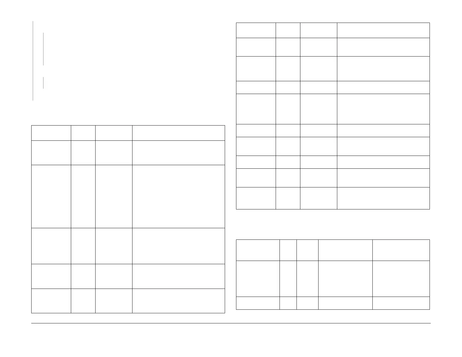
Refer to Figure 1 for the location and state of the LED’s on the single board controller PWB in a
non-fault condition.
Table 1 Single board controller PWB
LED ID
LED
colour
Fault State Description
CR1 Green Off 1.8V failure.
Indicates a voltage supply or regulation
fault. Install a new single board controller
PWB, PL 3.11 Item 13.
CR2 Red On (with a SIM
card installed)
NOTE: This LED is normally off if a SIM
card is installed, but flashes briefly when
the SIM card is accessed. If the LED does
not flash during SIM card access, this can
indicate a fault. If a SIM card is not installed,
this LED will be on.
The SIM card is corrupt or does not contain
the correct serial number. Install a new SIM
card of the same type, PL 3.11 Item 22.
Refer to GP 19.
CR3 Green Flashing Check that the SIM card serial number and
the machine chassis numbers match. Install
a new SIM card of the same type, PL 3.11
Item 22. Refer to GP 19.
If the fault persists, install a new single
board controller PWB, PL 3.11 Item 13.
CR4 Green Off Indicates +3.3V failure. Check harnesses
and install as necessary a new power distri
-
bution PWB, PL 3.11 Item 1 and a single
board controller PWB, PL 3.11 Item 13.
CR5 Green Off Indicates +3.3V failure. Check harnesses
and install as necessary a new power distri
-
bution PWB, PL 3.11 Item 1 and a single
board controller PWB, PL 3.11 Item 13.
CR7 Green A code appears A alpha-numeric codes appear in the win-
dow, refer to OF 16. The decimal point is
the heartbeat and pulses.
CR8 Green Off +1.8V SLEEP failure
Indicates a voltage supply or regulation
fault. Install a new single board controller
PWB, PL 3.11 Item 13.
CR9 Green Off Image clock disabled
CR12 Green Off Indicates a voltage supply or regulation
fault. Install a new single board controller
PWB, PL 3.11 Item 13. If CR4 or CR5 are
also off, install a new power distribution
PWB, PL 3.11 Item 1.
CR14 Red On Indicates power failure
CR24 Green On Indicates that the FPGA is not programmed.
Install a new single board controller PWB,
PL 3.11 Item 13.
CR10, CR11,
CR13
- - Not used
Internet connec-
tor left side PJ14 Green /
Yellow
Off
Check the ethernet cable. If necessary,
install a new single board controller PWB,
PL 3.11 Item 13.
Internet connec-
tor right side
PJ14
Green /
Yellow
Off
NOTE: This LED should be on or flashing
during data transfer.
Check the ethernet cable.
Table 2 7-Segment LED display
POST code name
Fault
code
Decimal
point
status
Code Description Service action
Display Test 8 On Initial 7 segment display
test
LED display or SBC PWB.
Check that the NVM mod-
ule PWB is fitted correctly,
PL 3.11 Item 17. Install a
new SBC PWB, PL 3.11
Item 13
PWBA 1 Off Failed explorer controller Install a new SBC PWB,
PL 3.11 Item 13.
Table 1 Single board controller PWB
LED ID
LED
colour Fault State Description

 Loading...