February 2013
4-159
ColorQube® 9303 Family
REP 12.28-171
Repairs/Adjustments
REP 12.28-171 BM Stapler Bracket Assembly
Parts List on PL 12.185.
Purpose
This procedure is used to repair the following parts:
• Front follower, PL 12.185 Item 1.
•Actuator, PL 12.185 Item 2.
• Rear follower, PL 12.185 Item 3.
• Spring, PL 12.185 Item 4.
• BM paper present sensor Q12-190, PL 12.185 Item 5.
• Latch slide, PL 12.185 Item 6.
• Staple bracket handle, PL 12.185 Item 9.
• Stapler bracket assembly, PL 12.185 Item 10.
• Torsion spring, PL 12.185 Item 11.
• Bearing, PL 12.185 Item 12.
• Spring, PL 12.185 Item 13.
• BM stapler head carrier closed sensor Q12-421, PL 12.185 Item 18.
• Lower shaft, PL 12.185 Item 19.
• Upper shaft, PL 12.185 Item 20.
Removal
WARNING
Take care during this procedure. Sharp edges may be present that can cause injury.
WARNING
Switch off the electricity to the machine GP 14. Disconnect the power cord from the cus-
tomer supply while performing tasks that do not need electricity. Electricity can cause
death or injury. Moving parts can cause injury.
1. Remove the top cover, then the rear cover, REP 12.1-171.
2. Remove 4 screws securing the BM PWB mounting plate to the frame, allow the PWB and
mounting plate to hang down, giving access to the BM staple head carrier closed sensor.
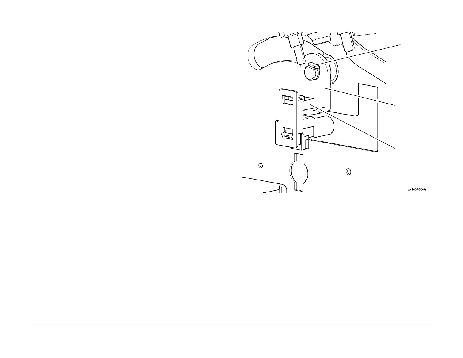
3. Figure 1, remove the BM staple head carrier closed sensor actuator.
Figure 1 Actuator removal
4. Temporarily attach the PWB mounting plate using only the top two screws.
5. Open the HVF BM front door and fully pull out the BM module.
6. Remove the crease blade knob (6d), PL 12.150 Item 4.
7. Remove the crease roll handle (6c), PL 12.150 Item 5.
8. Remove the BM front cover, PL 12.150 Item 3.
9. Remove both staple head covers, PL 12.185 Item 14.
1
Remove the
sensor.
2
Remove
the KL-clip.
3
Remove the
actuator.

 Loading...