February 2013
4-231
ColorQube® 9303 Family
REP 12.88-171, REP 12.89-171
Repairs/Adjustments
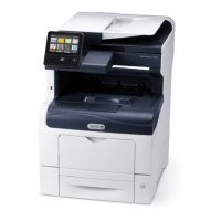
3. Remove the top cover door and the interlock switch, Figure 1.
Figure 1 Jam cover Interlock Switch
Replacement
1. Reverse the removal procedures to replace the jam cover interlock switch.
2. When reinstalling the top inside cover and the top cover door make sure that the correct
screws are used and that the screws are not overtightened.
REP 12.89-171 Main Tray and Paper Length Sensors
Parts List on PL 12.300.
Removal
WARNING
Take care during this procedure. Sharp edges may be present that can cause injury.
WARNING
Switch off the electricity to the machine. Refer to GP 14. Disconnect the power cord
from the customer supply while performing tasks that do not need electricity. Electricity
can cause death or injury. Moving parts can cause injury.
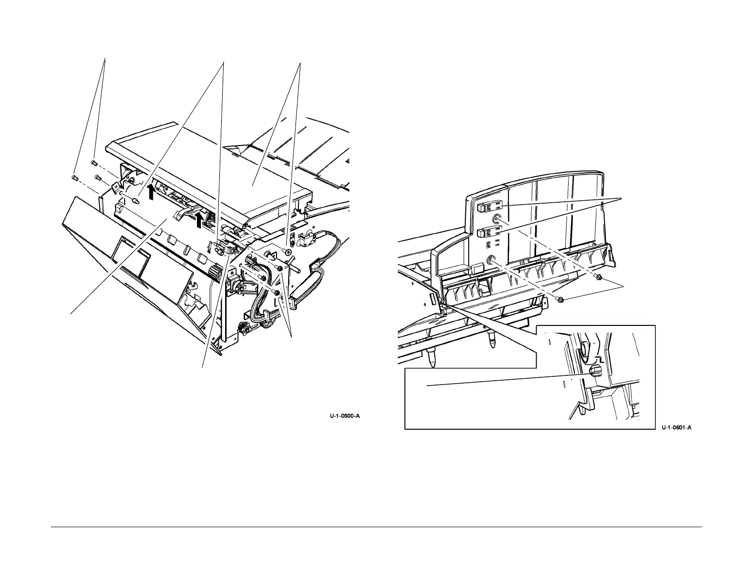
1. Pull the lug on one side of the tray to disconnect from the frame pivot. Remove the cover
plate then disconnect the PJs and remove the sensors from the bracket clips, Figure 1
Figure 1 Main Tray Assembly
Replacement
Reverse the removal procedures to replace the Inserter main tray and paper length sensors.
6
Remove the jam cover
interlock switch.
5
Release the cable harness
clips and lift the top inside
cover.
3
Remove 2 screws from
the rear.
2
Remove 2 latch
pins.
1
Remove the
rear pivot screw,
then the top
cover.
4
Remove 2 screws
from the front.
2
Remove 2 screws,
then the cover plate
3
Remove the rele-
vant paper length-
sensor.
1
Pull the lug on one side of the
tray to disconnect from the
frame pivot.

 Loading...