April 2010
4-31
Phaser 3635MFP/WorkCentre 3550
REP 10.3, REP 10.4
Repairs and Adjustments
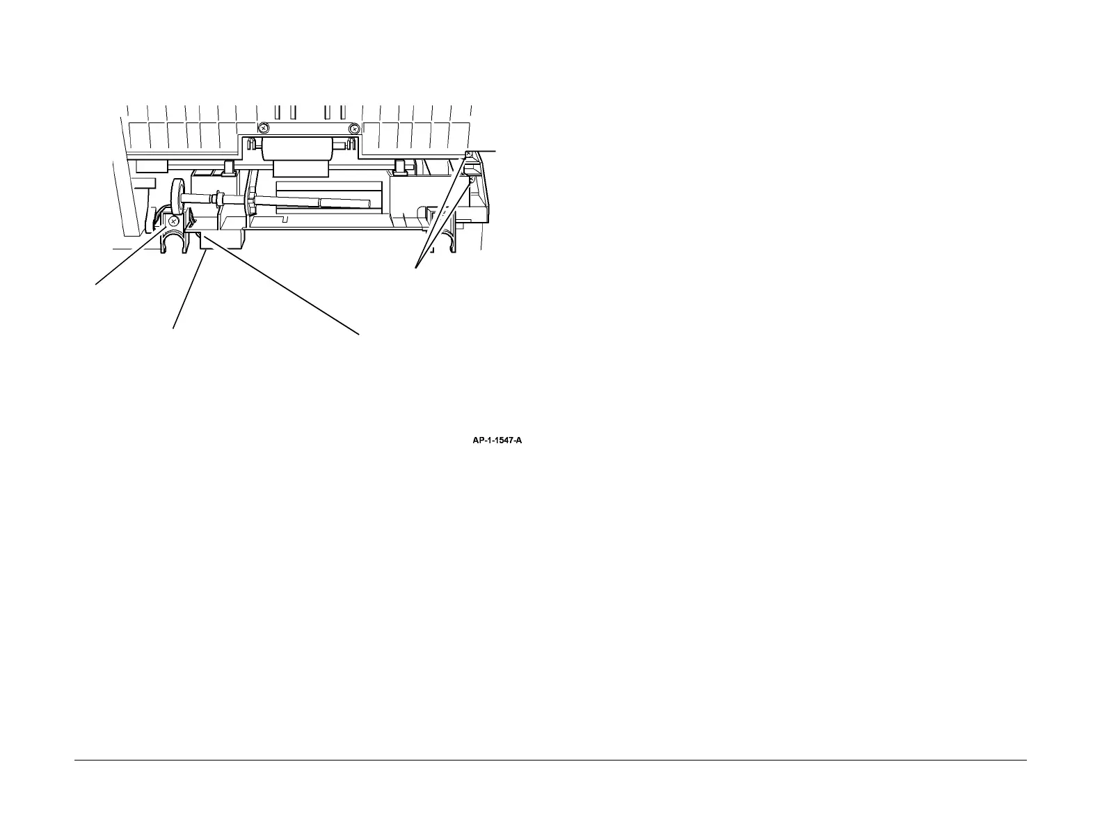
9. Remove the front duplex guide assembly, Figure 2.
Figure 2 Front duplex guide assembly removal
10. If necessary remove the tray 1 paper empty sensor, PL 10.22 Item 1 from the front duplex
guide.
Replacement
1. Replacement is the reverse of the removal procedure.
REP 10.4 Exit Roll and Exit Idler Assemblies
Parts List on PL 10.25
Removal
WARNING
Switch off the electricity to the machine. Disconnect the power cord from the customer
supply while performing tasks that do not need electricity. Electricity can cause death or
injury. Moving parts can cause injury.
CAUTION
Before performing this procedure, refer to GP 10 General Disassembly Precautions.
1. Remove the DADF, PL 5.10 Item 1.
2. Remove the left cover, right cover and rear cover, REP 28.1.
3. 3635 only. Remove the UI assembly, REP 2.1.
3550 only. Remove the UI assembly, REP 2.3.
4. Remove the scanner assembly, REP 14.1.
5. Remove the exit cover assembly, PL 28.10 Item 2.
6. Remove the exit roll, PL 10.25 Item 22.
7. Remove the idler assembly, PL 10.25 Item 21.
Replacement
1. Replacement is the reverse of the removal procedure.
2
Remove 2 screws.
1
Remove the
clamp.
3
Disconnect the
connector.
4
Remove the front duplex
guide assembly.

 Loading...