April 2010
4-41
Phaser 3635MFP/WorkCentre 3550
REP 28.1
Repairs and Adjustments
REP 28.1 External Covers
Parts List on PL 28.10
Removal
WARNING
Switch off the electricity to the machine. Disconnect the power cord from the customer
supply while performing tasks that do not need electricity. Electricity can cause death or
injury. Moving parts can cause injury.
CAUTION
Before performing this procedure, refer to GP 10 General Disassembly Precautions.
1. Remove the duplex assembly, PL 10.23 Item 18.
2. Remove the DADF, PL 5.10 Item 1.
3. Remove tray 1 PL 8.10 Item 1.
4. Remove the tray 2 module if present, PL 8.15 Item 28.
5. Remove the rear cover assembly, PL 28.10 Item 5 by removing 4 screws.
6. 3635 only. Remove the left trim, PL 14.10 Item 24 and the right trim, PL 14.10 Item 25.
NOTE: Figure 1 illustrates a Phaser 3635 MFP machine. However, the cover removal
procedures are identical for the WorkCentre 3550 machines.
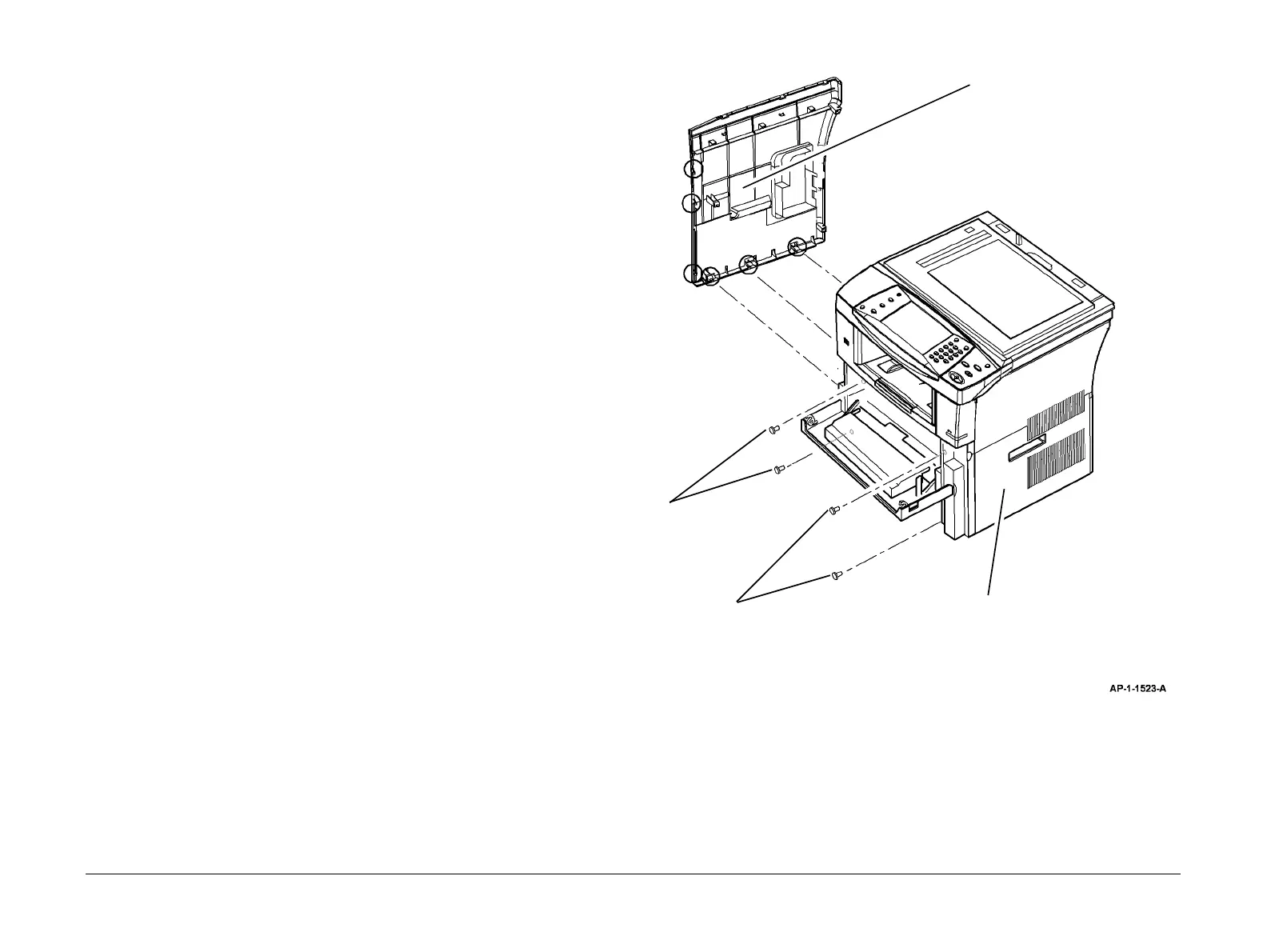
7. Remove the left cover or right cover as necessary, Figure 1.
Figure 1 Left and right covers removal
Replacement
1. Replacement is the reverse of the removal procedure.
2
Release 3 clips at the bottom
and 3 clips at the front, then
remove the left cover.
1
Remove 2 screws.
3
Remove 2 screws.
4
Release 3 clips at the bottom
and 4 clips at the front, then
remove the right cover.

 Loading...