April 2010
4-35
Phaser 3635MFP/WorkCentre 3550
REP 14.1
Repairs and Adjustments
REP 14.1 Scanner Assembly
Parts List on PL 14.10 (3635), PL 14.11 (3550)
Removal
WARNING
Switch off the electricity to the machine. Disconnect the power cord from the customer
supply while performing tasks that do not need electricity. Electricity can cause death or
injury. Moving parts can cause injury.
CAUTION
Before performing this procedure, refer to GP 10 General Disassembly Precautions.
1. Remove the DADF, PL 5.10 Item 1.
2. 3635 only. Remove the UI assembly, REP 2.1.
3550 only. Remove the UI assembly, REP 2.3.
3. Lock the CCD carriage.
4. Remove the rear cover assembly, left cover and right cover, REP 28.1.
5. 3635 only. Disconnect the following connectors from the Main PWB:
• CN1
• CN4
• CN5
• CN8
• CN9
• CN10
• CN12
3550 only. Disconnect the following connectors from the Main PWB:
• CN8
• CN16
• CN20
• CN21
• CN31
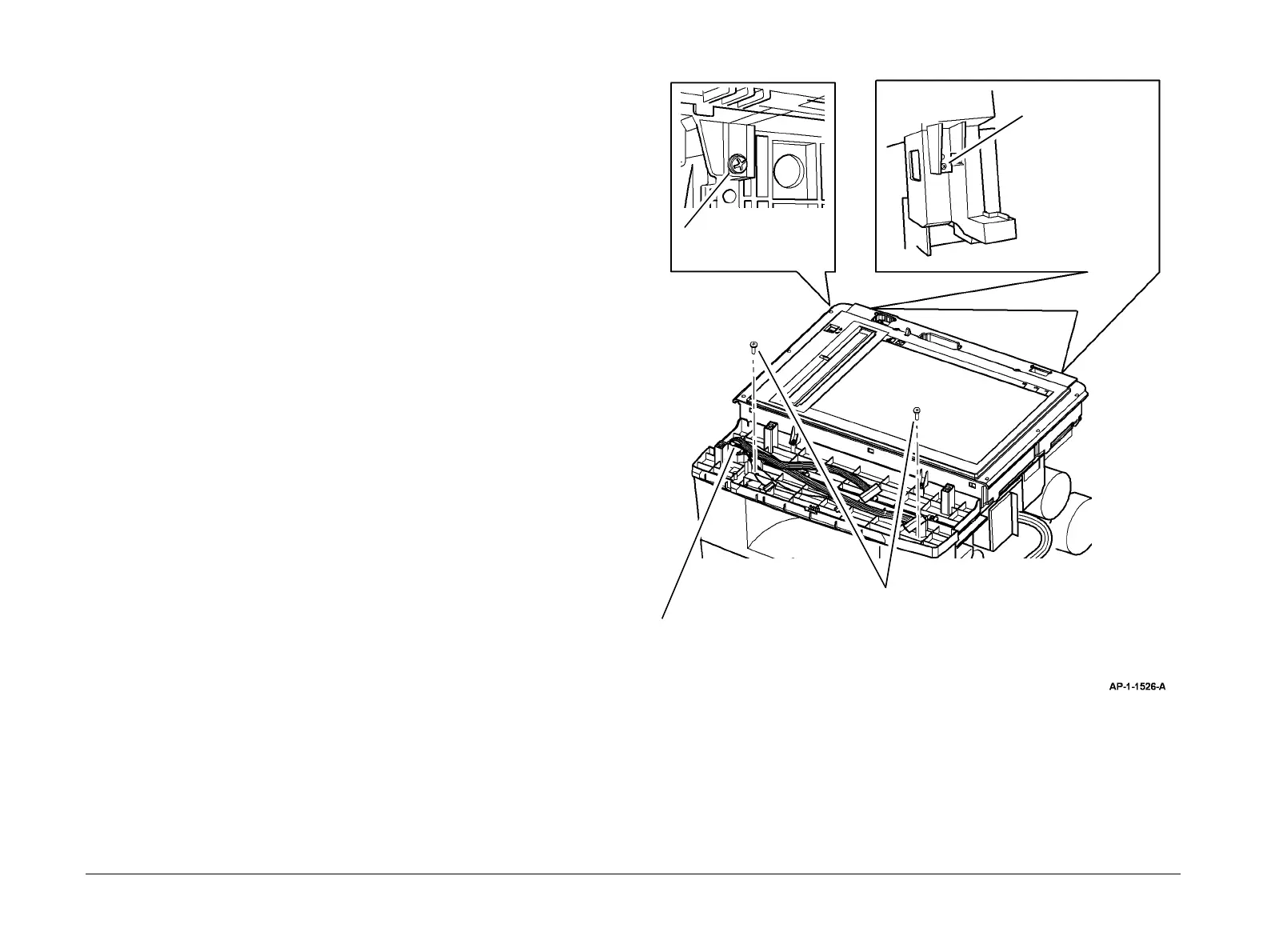
NOTE: Figure 1 illustrates a Phaser 3635 MFP type scanner. However, the removal pro-
cedure is identical for the WorkCentre 3550 machines.
6. Remove the scanner assembly, Figure 1.
Figure 1 Scanner assembly removal
Replacement
1. Replacement is the reverse of the removal procedure.
2. 3635 only. When reconnecting the ribbon cable to the main board (CN8) the blue flash
should face down.
3
Remove 2 screws.
4
Withdraw the UI harnesses through
the hole in the frame, then remove the
scanner assembly.
2
Remove 2 screws
from the rear.
1
Remove 1 screw.

 Loading...