April 2010
3-8
Phaser 3635MFP/WorkCentre 3550
IQ1, IQ2
Image Quality
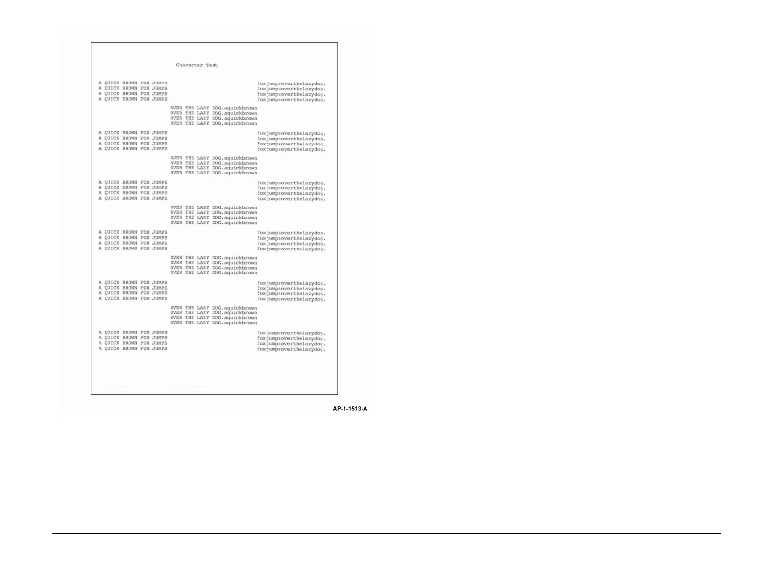
Figure 7 Test pattern 8 and 16
IQ2 Blank Copies RAP
Use this RAP when the machine produces blank copies.
Ensure the IQ1 Image Quality Entry RAP is performed before starting this RAP.
Procedure
WARNING
Switch off the electricity to the machine. Disconnect the power cord from the customer
supply while performing tasks that do not need electricity. Electricity can cause death or
injury. Moving parts can cause injury.
Go to the relevant procedure:
• 3635 Checkout
• 3550 Checkout
3635 Checkout
1. Determine the source of the problem. Make a print. Make a copy.
2. If the defect appears only in copy mode, perform the following:
a. If the defect appears only when using the DADF, check that the scanner lock, PL
14.10 Item 22 is completely unlocked.
b. Perform the Shading Test procedure, GP 15 Shading Test. If the shading test fails:
i. Install new components as necessary:
• CCD module, PL 14.10 Item 8.
• CCD module cable, PL 14.10 Item 23.
• Scanner assembly, PL 14.10 Item 26.
ii. Perform OF7 Main PWB Check RAP.
3. If the defect appears in all modes, perform the following:
a. Ensure the machine software is at version 20.100.29.000 or above.
b. Examine the print cartridge, PL 9.10 Item 1. Ensure it is free from all packing or seal-
ing material.
c. Check the LSU. Go to the 06-100, 06-200 LSU Error RAP.
d. Refer to Wiring Diagram 5 (3635) Perform the following:
• Check the wiring between the LSU and CN24 on the Main PWB.
• Install a new LSU, PL 6.10 Item 1.
e. Perform the following:
• Refer to Wiring Diagram 2. Remove the terminal cover, PL 9.10 Item 6, then
check the spring contacts between the HVPS PL 1.10 Item 3 and the print car-
tridge PL 9.10 Item 1. The spring contacts supply the voltages to the print car-
tridge. If necessary, clean the spring contacts.
• Check the following wiring:
– Wiring Diagram 1. Between CON3 on the SMPS and the CN6 on the Con-
nection PWB.
– Wiring Diagram 2. Between CN31 on the Main PWB and CN5 on the
HVPS.
– Wiring Diagram 6 (3635) Between CN5 on the Connection PWB and
CN26 on the Main PWB.
f. Install new components as necessary:

 Loading...