April 2010
4-42
Phaser 3635MFP/WorkCentre 3550
REP 28.2
Repairs and Adjustments
REP 28.2 Outbin Assembly
Parts List on PL 28.10
Removal
WARNING
Switch off the electricity to the machine. Disconnect the power cord from the customer
supply while performing tasks that do not need electricity. Electricity can cause death or
injury. Moving parts can cause injury.
WARNING
Take care during this procedure. Sharp edges may be present that can cause injury.
CAUTION
Before performing this procedure, refer to GP 10 General Disassembly Precautions.
1. Remove the DADF, PL 5.10 Item 1.
2. 3635 only. Remove the UI assembly, REP 2.1.
3550 only. Remove the UI assembly, REP 2.3.
3. Remove the left cover, right cover and rear cover, REP 28.1.
4. Remove the scanner assembly, REP 14.1.
5. 3550 only. Remove the stapler assembly, PL 11.10 Item 4.
6. 3635 only. Disconnect the following harnesses from the Connection PWB:
• CN1
• CN2
• CN6
• CN7
• CN8
3550 only. Disconnect the following harnesses from the Connection PWB:
• CN1
• CN3
• CN4
• CN5
• CN6
7. 3635 only. Disconnect the following harnesses from the Main PWB:
• CN2
• CN7
• CN14
• CN15
• CN26
3550 only. Disconnect the following harnesses from the Main PWB:
• CN12
• CN14
8. Remove the exit cover assembly, PL 28.10 Item 2.
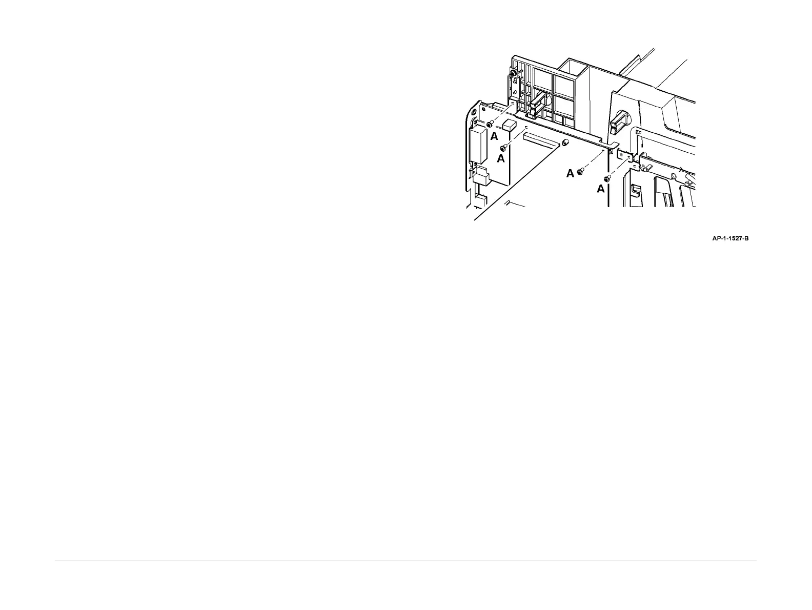
9. Prepare to remove the outbin assembly, Figure 1.
Figure 1 Preparation
CAUTION
Take care not to damage the main PWB location spigot when removing the outbin, refer to Fig-
ure 1. Also, take care not to move the exit roll and idlers.
1
Remove 4 screws marked A.
Main PWB location spigot

 Loading...