April 2010
4-21
Phaser 3635MFP/WorkCentre 3550
REP 7.1, REP 7.2
Repairs and Adjustments
REP 7.1 Bypass Feed Assembly
Parts List on PL 7.10
Removal
WARNING
Switch off the electricity to the machine. Disconnect the power cord from the customer
supply while performing tasks that do not need electricity. Electricity can cause death or
injury. Moving parts can cause injury.
CAUTION
Before performing this procedure, refer to GP 10 General Disassembly Precautions.
1. Remove the DADF, PL 5.10 Item 1.
2. 3635 only. Remove the UI assembly, REP 2.1.
3550 only. Remove the UI assembly, REP 2.3.
3. Remove the scanner assembly, REP 14.1.
4. Remove the front cover assembly, PL 28.10 Item 7.
5. Remove the front mid cover, REP 28.3.
6. 3635 only. Disconnect CN37 from the Main PWB.
3550 only. Disconnect CN28 from the Main PWB.
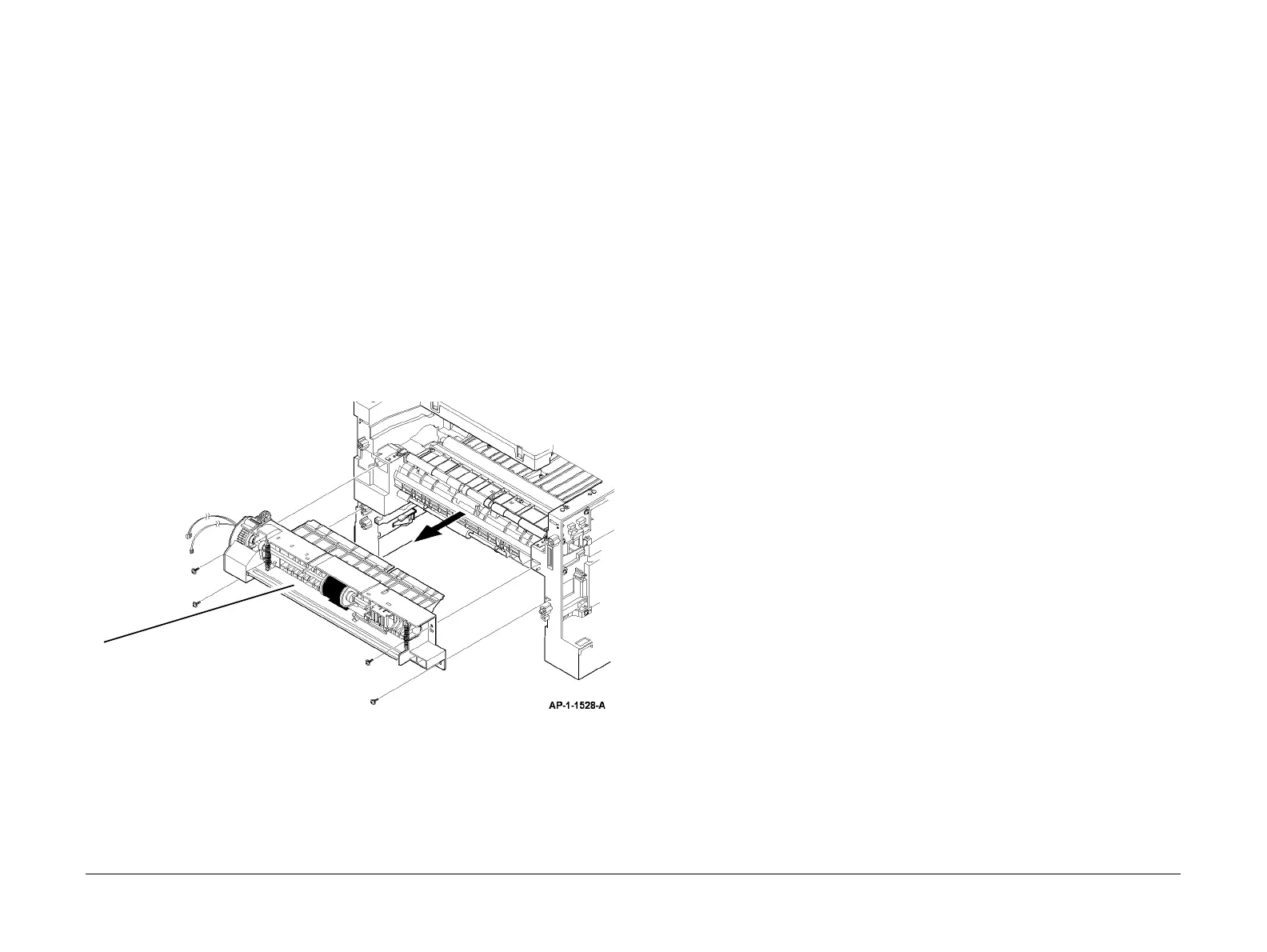
7. Remove the bypass feed assembly, Figure 1.
Figure 1 Bypass feed removal
Replacement
1. Replacement is the reverse of the removal procedure.
REP 7.2 Registration Solenoid and Tray 1 Pickup Solenoid
Parts List on PL 8.25
Removal
WARNING
Switch off the electricity to the machine. Disconnect the power cord from the customer
supply while performing tasks that do not need electricity. Electricity can cause death or
injury. Moving parts can cause injury.
WARNING
Take care during this procedure. Sharp edges may be present that can cause injury.
CAUTION
Before performing this procedure, refer to GP 10 General Disassembly Precautions.
1. Remove the left cover, REP 28.1.
2. Remove the main drive assembly, refer to REP 4.1.
3. 3635 only. Disconnect CN36 on the Main PWB.
3550 only. Disconnect CN29 on the Main PWB.
4. Remove the relevant component:
• Tray 1 pickup solenoid, PL 8.25 Item 19.
• Registration solenoid, PL 8.25 Item 18.
Replacement
1. Replacement is the reverse of the removal procedure.
1
Remove 4 screws, then remove the
bypass feed assembly.

 Loading...