20
E
SPEC
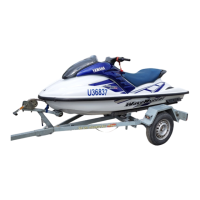
Side ornament Screw M5 4 2.2 0.22 1.6
Center cover Nut — 4 5.4 0.54 3.9
Hood lock Nut — 2 6.4 0.64 4.6
Compass sensor and air tempera-
ture sensor
Nut — 2 3.8 0.38 2.7
Shift lever assembly Nut — 3 5.4 0.54 3.9
Seat lock assembly Bolt M6 4 6.4 0.64 4.6
271
LT
Deck beam Nut — 4 18 1.8 13
Projection Nut — 2 26 2.6 19
Rear seat stay Nut — 4 6.4 0.64 4.6
Front seat stay Nut — 2 15 1.5 11
Hand grip Nut — 4 5.4 0.54 3.9
Spout Nut — 1 5.4 0.54 3.9
Cleat Nut — 6 15 1.5 11
Sponson Bolt M8 10 16 1.6 12
271
LT
Drain plug/screw Screw M5 4 2.0 0.2 1.4
Bow eye Bolt M6 2 13 1.3 9.4
572
LT
Reboarding step Bolt M8 6 15 1.5 11
271
LT
Front protector 1 Nut — 3 5.4 0.54 3.9
Front protector 2/3 Nut — 4 5.4 0.54 3.9
Cleat Bolt M6 6 2.4 0.24 1.7
Part to tightened Part name
Thread
size
Q’ty
Tightening torque
Remarks
N•m kgf•m ft•lb
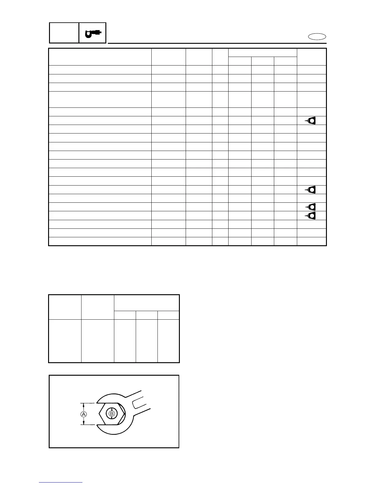
TIGHTENING TORQUES
GENERAL TORQUE
This chart specifies tightening torques for stan-
dard fasteners with a standard ISO thread
pitch. Tightening torque specifications for spe-
cial components or assemblies are provided in
applicable sections of this manual. To avoid
warpage, tighten multi-fastener assemblies in
a crisscross fashion and progressive stages
until the specified tightening torque is reached.
Unless otherwise specified, tightening torque
specifications require clean, dry threads.
Components should be at room temperature.
Nut
A
Bolt
B
General torque
specifications
N•m kgf•m ft•lb
8 mm M5 5.0 0.5 3.6
10 mm M6 8.0 0.8 5.8
12 mm M8 18 1.8 13
14 mm M10 36 3.6 26
17 mm M12 43 4.3 31
 Loading...