2-17
E
SPEC
TIGHTENING TORQUES
Bracket (coupler) – electrical box
Tapping
screw
ø6 1 3.9 0.39 2.8
Slant detection switch – electrical
box
Tapping
screw
ø6 2 3.9 0.39 2.8
Main and fuel pump relay –
electrical box
Tapping
screw
ø6 1 3.9 0.39 2.8
Rectifier/regulator – electrical box
Tapping
screw
ø6 2 3.9 0.39 2.8
Ignition coil – cylinder head cover Bolt M6 4 7.6 0.76 5.5
572
LT
Brush assembly/spacer –
starter motor yoke
Nut — 1 8.8 0.88 6.4
Starter motor rear cover –
starter motor front cover
Bolt M5 2 6.4 0.64 4.6
Cover – remote control transmitter
Tapping
screw
ø2 6 0.1 0.01 0.07
Part to tightened Part name
Thread
size
Q’ty
Tightening torque
Remarks
N•m kgf•m ft•lb
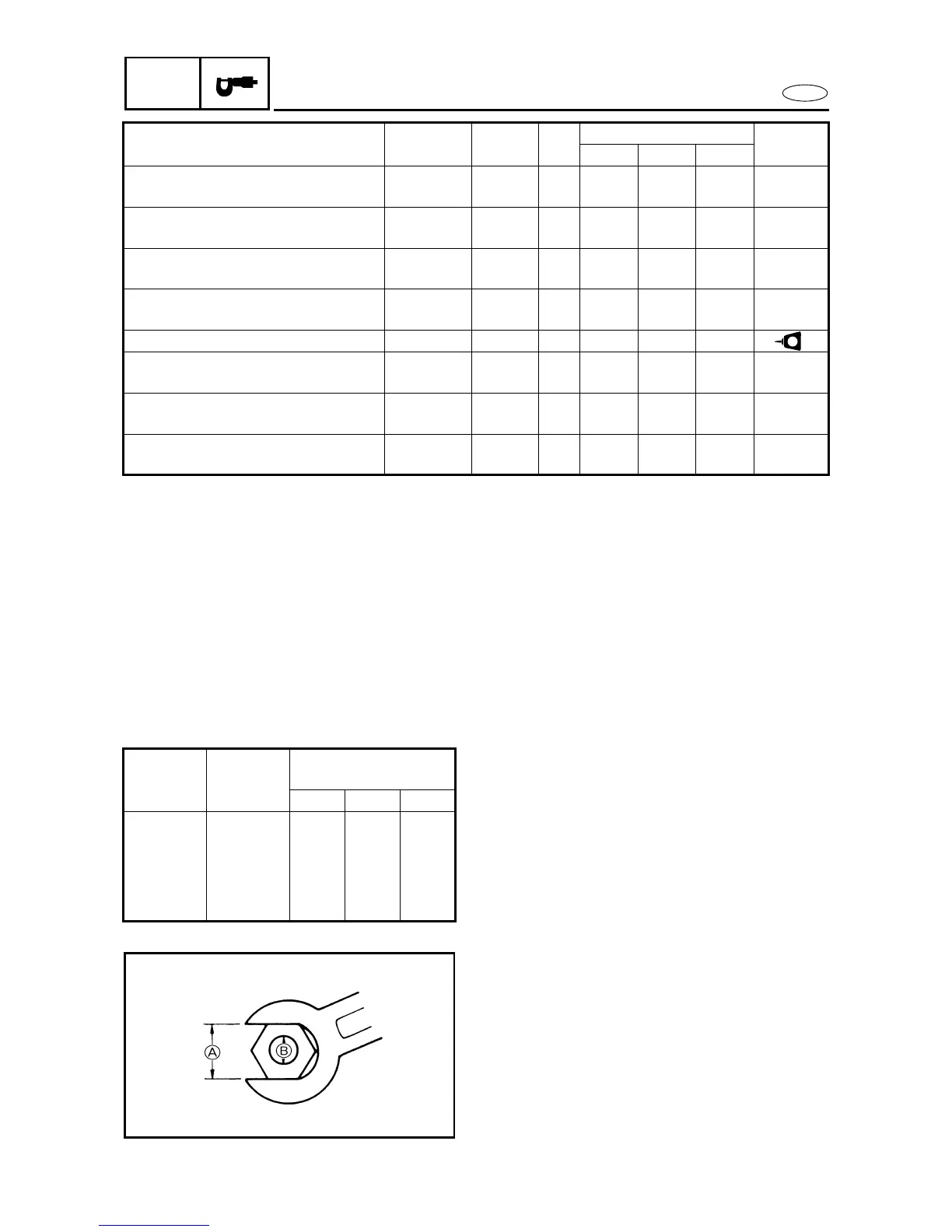
GENERAL TORQUE
This chart specifies tightening torques for stan-
dard fasteners with a standard ISO thread
pitch. Tightening torque specifications for spe-
cial components or assemblies are provided in
applicable sections of this manual. To avoid
warpage, tighten multi-fastener assemblies in
a crisscross fashion and progressive stages
until the specified tightening torque is reached.
Unless otherwise specified, tightening torque
specifications require clean, dry threads.
Components should be at room temperature.
Nut
A
Bolt
B
General torque
specifications
N•m kgf•m ft•lb
8 mm M5 5.0 0.5 3.6
10 mm M6 8.0 0.8 5.8
12 mm M8 18 1.8 13
14 mm M10 36 3.6 25
17 mm M12 43 4.3 31