76
E
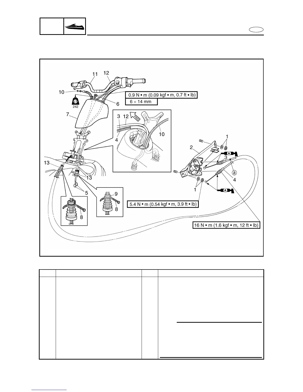
HULL
HOOD
HANDLEBAR
EXPLODED DIAGRAM
REMOVAL AND INSTALLATION CHART
Step
Procedure/Part name
Q’ty Service points
HANDLEBAR REMOVAL
Follow the left “Step” for removal.
QSTS cable (to jet thrust nozzle) Refer to “REMOTE CONTROL CABLES
AND SPEED SENSOR LEAD”.
1 Nut/washer 2/2
2 QSTS converter 1
3 QSTS cable 2 1 With white tape
a
4 QSTS cable 1 1
NOTE:
• Route the QSTS cables through the star-
board side in the steering console.
• Route the handlebar switch lead, and throt-
tle cable through the port side in the steer-
ing console.
5 Handlebar switch coupler 2




 To Next Page