79
E
HULL
HOOD
HANDLEBAR
SERVICE POINTS
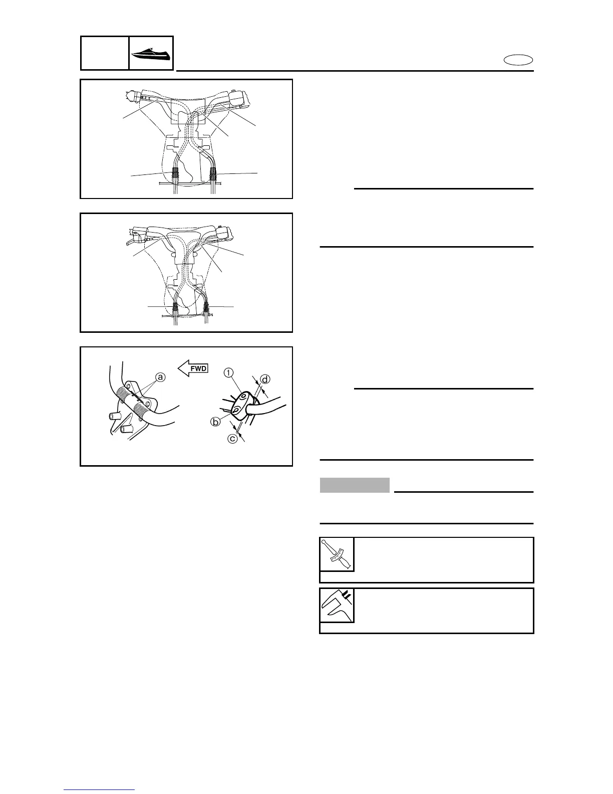
Handlebar assembly installation
1. Install:
• Plastic ties
1
• QSTS cables
2
• Handlebar switch lead
3
• Throttle cable
4
NOTE:
After inserting the QSTS cables, handlebar
switch lead and throttle cable into the grom-
mets, tie the end of grommets with the plastic
ties.
È FX/FX High Output
É FX Cruiser/FX Cruiser High Output
2
3
4
1
1
È
1
4
1
2
3
É
2. Install:
• Upper handlebar holder
1
NOTE:
• Align the punch marks
a on the handlebar
with the top surface of the handlebar holder.
• The upper handlebar holder should be
installed with the punch mark b facing for-
ward.
CAUTION:
Clearance
c
should be narrower than
clearance
d
.
T
R
.
Handlebar holder bolt:
20 N • m (2.0 kgf • m, 14 ft • lb)
LOCTITE 242
Reference clearance:
c
: 1.5 mm (0.06 in)
d
: 3.5 mm (0.14 in)



 To Next Page