WIRING DIAGRAM
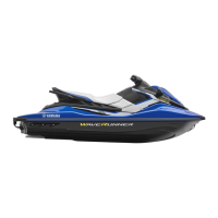
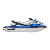
FX High Output/FX Cruiser High Output
1 Fuse (20 A)
2 Fuse (3 A)
3 Starter relay
4 Noise filter
5 Cam position sensor
6 Oil pressure switch
7 Thermoswitch (exhaust)
8 Sensor assembly
(intake air pressure, intake air temperature)
9 Bypass valve motor
0 Fuel injector
A Throttle position sensor
B Pickup coil
C Lighting coil
D Remote control unit
E Antenna
F Engine stop switch
G Engine shut-off switch
H Start switch
I Left operation button
J Multifunction meter
K Right operation button
(FX Cruiser High Output)
L Steering sensor
M Compass sensor and air temperature sensor
(FX Cruiser High Output)
N Speed sensor (FX High Output)
Speed sensor and water temperature sensor
(FX Cruiser High Output)
O Buzzer
P Fuel level sensor
Q Fuel pump
R Thermoswitch (engine)
S Starter motor
T Engine temperature sensor
U Ignition coil
V Spark plug
W Rectifier/regulator
X Battery
Y Electric bilge pump
Z ECM
[ Slant detection switch
\ Main and fuel pump relay
È To tachometer
É To entry box
Ê FX Cruiser High Output model
Color code
B: Black
Br : Brown
G: Green
Gy : Gray
L: Blue
O : Orange
P: Pink
R: Red
W: White
Y : Yellow
B/G : Black/green
B/L : Black/blue
B/O : Black/orange
B/R : Black/red
B/W : Black/white
B/Y : Black/yellow
G/B : Green/black
G/O : Green/orange
G/R : Green/red
G/W : Green/white
G/Y : Green/yellow
L/B : Blue/black
L/R : Blue/red
L/Y : Blue/yellow
P/G : Pink/green
P/W : Pink/white
Pu/B : Purple/black
Pu/G : Purple/green
Pu/R : Purple/red
Pu/W : Purple/white
Pu/Y : Purple/yellow
R/Y : Red/yellow
R/W : Red/white
W/B : White/black
W/L : White/blue
W/R : White/red
Y/W : Yellow/white



 To Next Page