■ Sequence Circuit Configuration Example
The braking sequence should be designed as follows:
• A normally open signal (N.O.) should be used to control the brake so that it is released when terminal M1-M2 closes.
• When a fault signal is output, the brake should close.
Figure 4.12
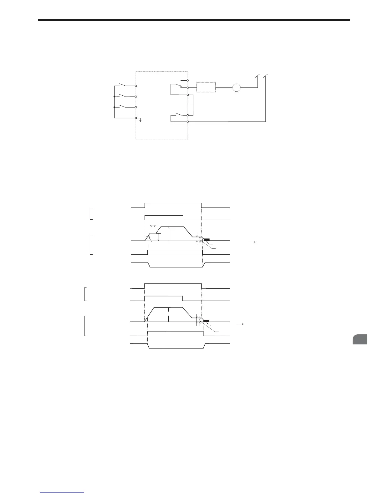
Figure 4.13 Sequence Circuit Configuration
• The brake should release just a bit after the Run command is issued, allowing the motor to build up torque. If using the
V/f, V/f w PG or OLV control modes and the “Frequency detection 2” signal controls the brake, the motor can be given
time to build up torque by setting the brake release level in parameter L4-01. Additionally, DC Injection Braking at
start can be applied. If using CLV or CLV/PM and the “During frequency output” signal controls the brake, initial
excitation should be enabled. Set the initial excitation time to parameter b2-03.
• The time chart below gives a an example sequence.
Figure 4.13
Figure 4.14 Holding Brake Time Chart (V/f, V/f w/PG, OLV)
Figure 4.14
Figure 4.15 Holding Brake Time Chart (CLV, CLV/PM)

 Loading...


