3.8 Main Circuit Wiring
This section describes the functions, specifications, and procedures required to safely and properly wire the main circuit
in the drive.
NOTICE: Do not solder the ends of wire connections to the drive. Soldered wiring connections can loosen over time. Improper wiring
practices could result in drive malfunction due to loose terminal connections.
NOTICE: Do not switch the drive input to start or stop the motor. Frequently switching the drive on and off shortens the lifetime of the
DC bus charge circuit and the DC bus capacitors, and can cause premature drive failures. For the full performance life, refrain from
switching the drive on and off more than once every 30 minutes.
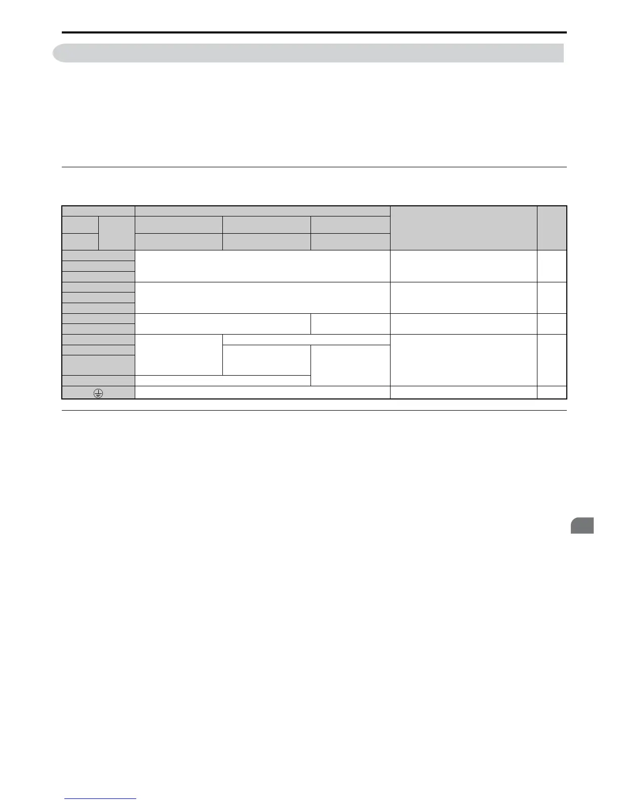
◆ Main Circuit Terminal Functions
Table 3.1 Main Circuit Terminal Functions
◆ Protecting Main Circuit Terminals
■ Insulation Cap
Use insulation caps when wiring the drive with crimp terminals. Take particular care to ensure that wiring does not touch
neighboring terminals or the surrounding case.
Terminal Type
Function Page
200 V
Class
Model
CIMR-A
2A0004 to 2A0081 2A0110, 2A0138 2A0169 to 2A0415
400 V
Class
4A0002 to 4A0044 4A0058 to 4A0072 4A0088 to 4A0675
R/L1
Main circuit power supply input Connects line power to the drive 54
S/L2
T/L3
U/T1
Drive output Connects to the motor 54
V/T2
W/T3
B1
Braking resistor not available
Available for connecting a braking resistor or a
braking resistor unit option
379
B2
+2 • DC reactor connection (+1,
+2) (remove the shorting bar
between +1 and +2)
• DC power supply input
(+1, –)
not available
For connection
• of the drive to a DC power supply (terminals +1
and – are not EU or UL approved)
• of dynamic braking options
• of a DC reactor
383
+1
• DC power supply input
(+1, –)
• DC power supply input
(+1, –)
• Braking unit connection
(+3, –)
–
+3 not available
– Grounding terminal 71

 Loading...


