3.8 Main Circuit Wiring
70 YASKAWA ELECTRIC SIEP C710616 27C YASKAWA AC Drive A1000 Technical Manual
◆ Main Circuit Terminal and Motor Wiring
This section outlines the various steps, precautions, and checkpoints for wiring the main circuit terminals and motor
terminals.
NOTICE: When connecting the motor to the drive output terminals U/T1, V/T2, and W/T3, the phase order for the drive and motor
should match. Failure to comply with proper wiring practices may cause the motor to run in reverse if the phase order is backward.
NOTICE: Do not connect phase-advancing capacitors or LC/RC noise filters to the output circuits. Failure to comply could result in
damage to the drive, phase-advancing capacitors, LC/RC noise filters or ground fault circuit interrupters.
NOTICE: Do not connect the AC power line to the output motor terminals of the drive. Failure to comply could result in death or serious
injury by fire as a result of drive damage from line voltage application to output terminals.
■ Cable Length Between Drive and Motor
Voltage drop along the motor cable may cause reduced motor torque when the wiring between the drive and the motor is
too long, especially at low frequency output. This can also be a problem when motors are connected in parallel with a
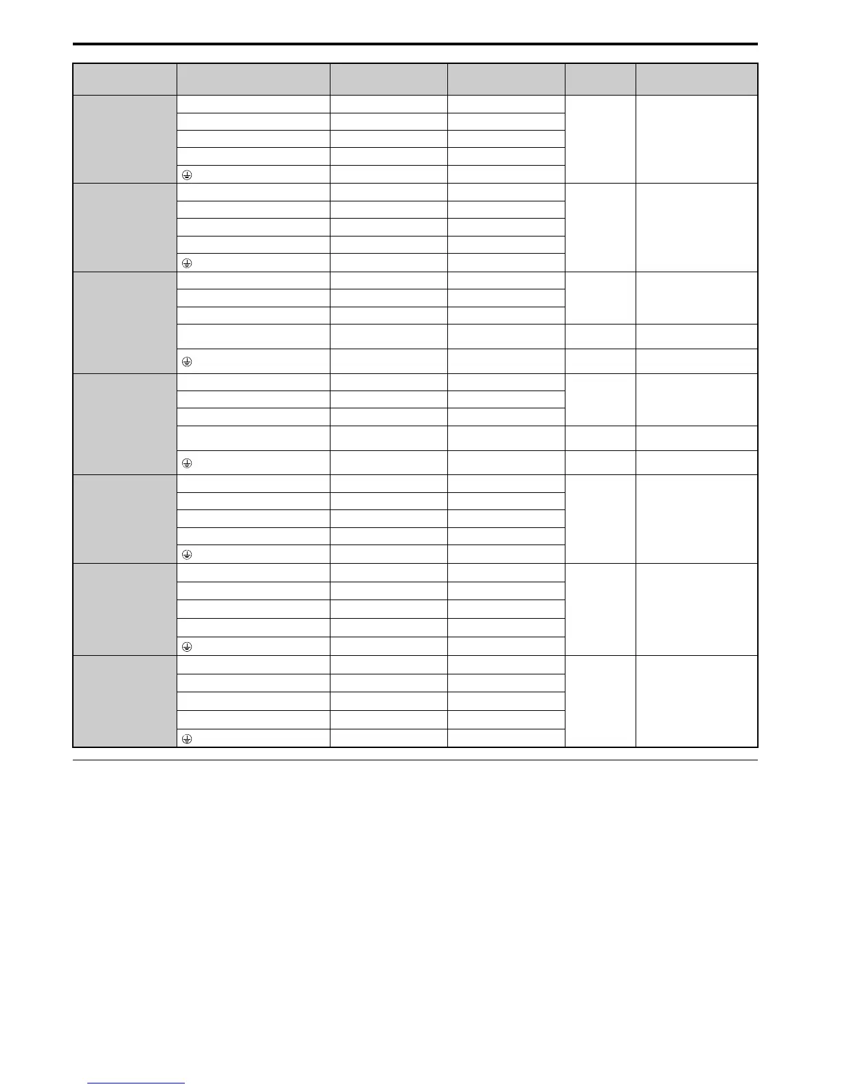
4A0208
R/L1, S/L2, T/L3 95 35 to 95
M10
18 to 23
(159 to 204)
U/T1, V/T2, W/T3 95 35 to 95
–, +1 – 35 to 150
+3 – 25 to 70
50 50 to 150
4A0250
R/L1, S/L2, T/L3 120 95 to 300
M10
18 to 23
(159 to 204)
U/T1, V/T2, W/T3 120 95 to 300
–, +1 – 70 to 300
+3 – 35 to 300
70 70 to 240
4A0296
R/L1, S/L2, T/L3 185 95 to 300
M12
32 to 40
(283 to 354)
U/T1, V/T2, W/T3 185 95 to 300
–, +1 – 70 to 300
+3 – 35 to 300 M10
18 to 23
(159 to 204)
95 95 to 240 M12
32 to 40
(283 to 354)
4A0362
R/L1, S/L2, T/L3 240 95 to 300
M12
32 to 40
(283 to 354)
U/T1, V/T2, W/T3 240 95 to 300
–, +1 – 95 to 300
+3 – 70 to 300 M10
18 to 23
(159 to 204)
120 120 to 240 M12
32 to 40
(283 to 354)
4A0414
R/L1, S/L2, T/L3 95 × 2P 95 to 150
M12
32 to 40
(283 to 354)
U/T1, V/T2, W/T3 95 × 2P 95 to 150
–, +1 – 70 to 150
+3 – 70 to 150
95 35 to 95
4A0515
R/L1, S/L2, T/L3 120 × 2P 95 to 150
M12
32 to 40
(283 to 354)
U/T1, V/T2, W/T3 150 × 2P 95 to 150
–, +1 – 70 to 150
+3 – 70 to 150
150 50 to 150
4A0675
R/L1, S/L2, T/L3 95 × 4P 95 to 150
M12
32 to 40
(283 to 354)
U/T1, V/T2, W/T3 95 × 4P 95 to 150
–, +1 – 70 to 150
+3 – 70 to 150
95 × 2P 60 to 150
Model
CIMR-A
Terminal
Recommended Gauge
mm
2
Applicable
Gauge
mm
2
Screw
Size
Tightening
Torque
Nxm (lb.in.)

 Loading...


