214 YASKAWA ELECTRIC SIEP C710616 27C YASKAWA AC Drive A1000 Technical Manual
5.7 H: Terminal Functions
5.7 H: Terminal Functions
H parameters are used to assign functions to the external terminals.
◆ H1: Multi-Function Digital Inputs
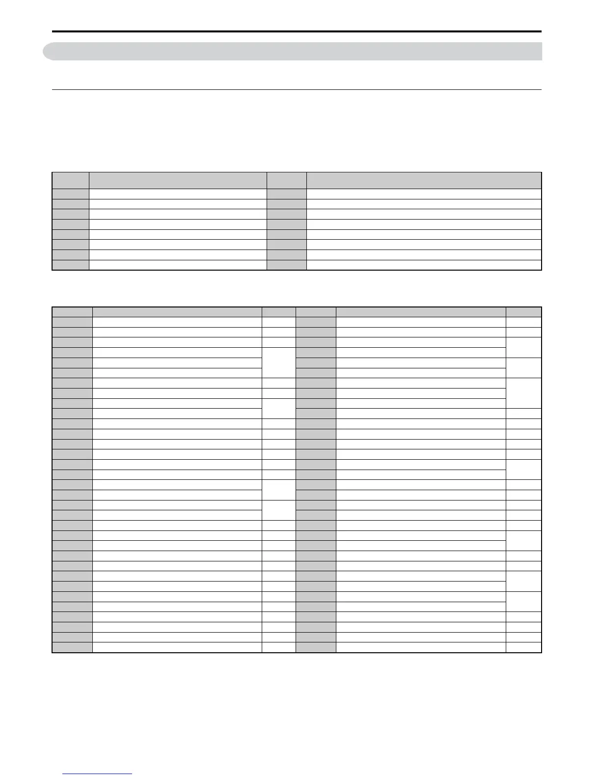
■ H1-01 to H1-08: Functions for Terminals S1 to S8
These parameters assign functions to the multi-function digital inputs. The various functions and their settings are listed
below in Table 5.35 .
Table 5.35 Multi-Function Digital Input Terminal Settings
No.
<1> Number appearing in parenthesis is the default value after performing a 3-Wire initialization.
Parameter Name
Setting
Range
Default
H1-01 Multi-Function Digital Input Terminal S1 Function Selection 1 to 9F 40 (F) <1>: Forward Run Command (2-wire sequence)
H1-02 Multi-Function Digital Input Terminal S2 Function Selection 1 to 9F 41 (F) <1>: Reverse Run Command (2-wire sequence)
H1-03 Multi-Function Digital Input Terminal S3 Function Selection 0 to 9F 24: External Fault
H1-04 Multi-Function Digital Input Terminal S4 Function Selection 0 to 9F 14: Fault Reset
H1-05 Multi-Function Digital Input Terminal S5 Function Selection 0 to 9F 3 (0) <1>: Multi-Step Speed Reference 1
H1-06 Multi-Function Digital Input Terminal S6 Function Selection 0 to 9F 4 (3) <1>: Multi-Step Speed Reference 2
H1-07 Multi-Function Digital Input Terminal S7 Function Selection 0 to 9F 6 (4) <1>: Jog Reference Selection
H1-08 Multi-Function Digital Input Terminal S8 Function Selection 0 to 9F 8: External Baseblock Command
Setting Function Page Setting Function Page
0 3-wire sequence 215 34 PID soft starter cancel 221
1 Local/remote selection 215 35 PID input level selection 221
2 External reference 1/2 selection 216 40 Forward run command (2-wire sequence)
221
3 Multi-Step Speed Reference 1
216
41 Reverse run command (2-wire sequence)
4 Multi-Step Speed Reference 2 42 Run command (2-wire sequence 2)
221
5 Multi-Step Speed Reference 3 43 FWD/REV command (2-wire sequence 2)
6 Jog reference selection 216 44 Offset frequency 1
221
7 Accel/decel time selection 1 216 45 Offset frequency 2
8 Baseblock command (N.O.)
216
46 Offset frequency 3
9 Baseblock Command (N.C.) 47 Node setup 221
A Accel/decel ramp hold 216 60 DC Injection Braking command 222
B Drive overheat alarm (OH2) 217 61 External Speed Search command 1 222
C Analog terminal input selection 217 62 External Speed Search command 2 222
D PG encoder disable 217 63 Field Weakening 222
E ASR integral reset 217 65 KEB Ride-Thru 1 (N.C.)
222
F Through mode 217 66 KEB Ride-Thru 1 (N.O.)
10 Up command
217
67 Communications test mode 222
11 Down command 68 High Slip Braking 222
12 Forward jog
218
6A Drive enabled 222
13 Reverse jog 71 Speed/Torque Control switch 223
14 Fault reset 218 72 Zero Servo 223
15 Fast Stop (N.O.) 218 75 Up 2 command
223
16 Motor 2 selection 219 76 Down 2 command
17 Fast Stop (N.C.) 218 77 ASR gain switch 223
18 Timer function input 219 78 External torque reference polarity inversion 223
19 PID disable 219 7A KEB Ride-Thru 2 (N.C.)
224
1A Accel/decel time selection 2 220 7B KEB Ride-Thru 2 (N.O.)
1B Program lockout 220 7C Short Circuit Braking (N.O.)
224
1E Reference sample hold 220 7D Short Circuit Braking (N.C.)
20 to 2F External fault 220 7E Forward/reverse detection (V/f control with simple PG) 224
30 PID integral reset 221 7F Bi-directional PID output enable 224
31 PID integral hold 221 90 to 97 DriveWorksEZ Digital input 1 to 8 224
32 Multi-step speed reference 4 221 9F DriveWorksEZ disabled 224

 Loading...


