3.8 Main Circuit Wiring
66 YASKAWA ELECTRIC SIEP C710616 27C YASKAWA AC Drive A1000 Technical Manual
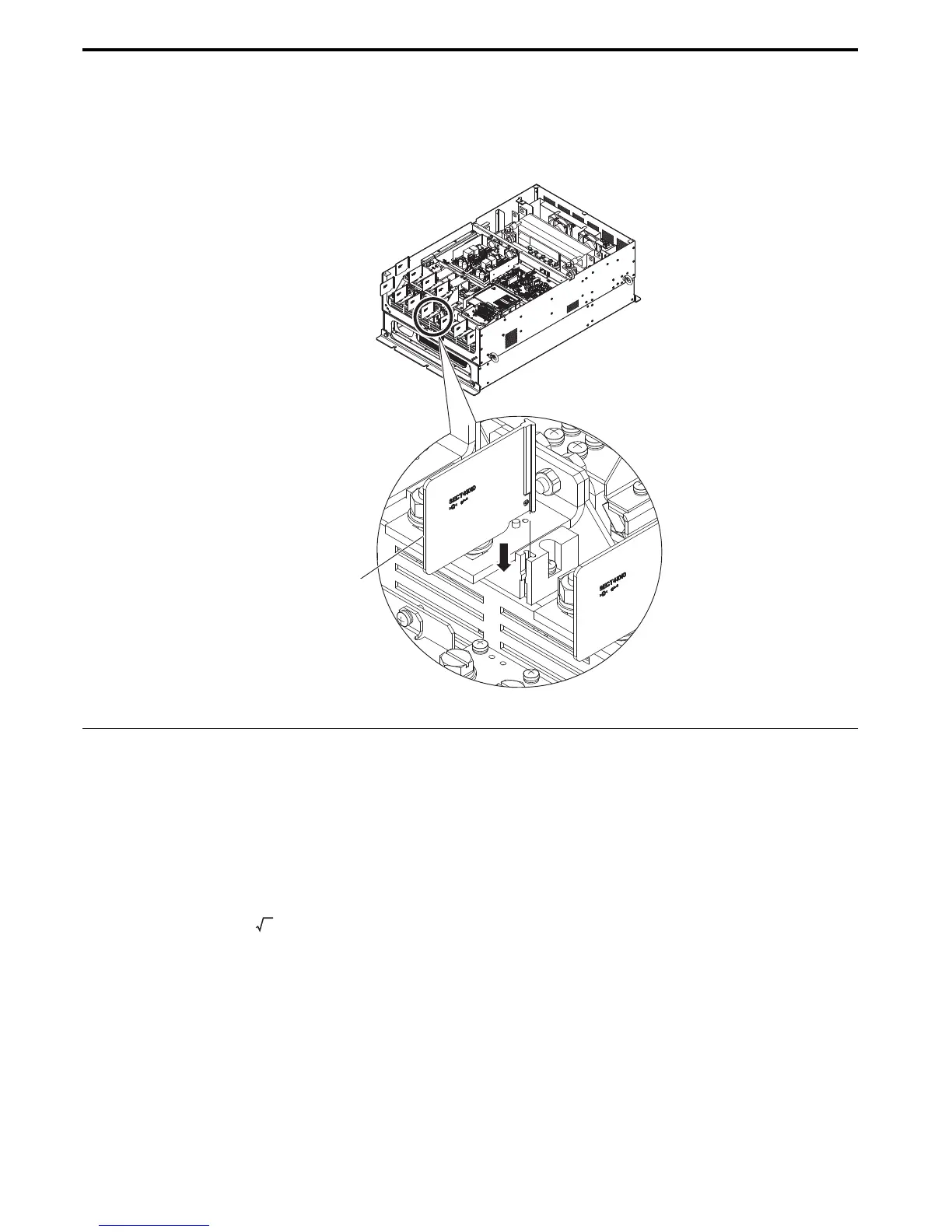
■ Insulation Barrier
Insulation barriers are packaged with drive models CIMR-A4A0414 through 0675 to provide added protection
between terminals. Yaskawa recommends using the insulation barriers provided to ensure proper wiring. See Figure 3.20
for instructions on where the insulation barriers should be placed.
Figure 3. 24
Figure 3.20 Installing insulation barriers
◆ Wire Gauges and Tightening Torque
Select the appropriate wires and crimp terminals from through .
Note: 1. Wire gauge recommendations based on drive continuous current ratings (ND) using 75°C 600 Vac vinyl-sheathed wire assuming
ambient temperature within 40°C and wiring distance less than 100 m.
2. Terminals +1, +2, +3, –, B1 and B2 are for connecting optional devices such as a DC reactor or braking resistor. Do not connect other
nonspecific devices to these terminals.
• Consider the amount of voltage drop when selecting wire gauges. Increase the wire gauge when the voltage drop is
greater than 2% of motor rated voltage. Ensure the wire gauge is suitable for the terminal block. Use the following
formula to calculate the amount of voltage drop:
Line drop voltage (V) = × wire resistance (Ω/km) × wire length (m) × current (A) × 10
-3
• Refer to instruction manual TOBPC72060000 for braking unit or braking resistor unit wire gauges.
• Use terminal +1 and the negative terminal when connecting a braking resistor, regenerative converter, or a regen unit.
• Refer to UL Standards Compliance on page 515 for information on UL compliance.
Insulation Barrier

 Loading...


