B.3 Parameter Table
414 YASKAWA ELECTRIC SIEP C710616 27C YASKAWA AC Drive A1000 Technical Manual
■ d7: Offset Frequency
◆ E: Motor Parameters
■ E1: V/f Pattern for Motor 1
No.(Addr.) Name Description Setting Page
d7-01
(2B2H)
Offset Frequency 1
Added to the frequency reference when the digital input “Frequency offset 1” (H1- = 44) is
switched on.
Default: 0.0%
Min: -100.0%
Max: 100.0%
193
d7-02
(2B3H)
Offset Frequency 2
Added to the frequency reference when the digital input “Frequency offset 2” (H1- = 45) is
switched on.
Default: 0.0%
Min: -100.0%
Max: 100.0%
193
d7-03
(2B4H)
Offset Frequency 3
Added to the frequency reference when the digital input “Frequency offset 3” (H1- = 46) is
switched on.
Default: 0.0%
Min: -100.0%
Max: 100%
193
No.(Addr.) Name Description Setting Page
E1-01
(300H)
<3> Parameter setting value is not reset to the default value when the drive is initialized.
<4> Default setting is dependent on the control mode (A1-02), the drive model (o2-04), and the Drive Duty (C6-01).
<14> Default setting value is dependent on the motor code set to E5-01.
Input Voltage Setting
This parameter must be set to the power supply voltage.
WARNING! Drive input voltage (not motor voltage) must be set in E1-01 for the protective
features of the drive to function properly. Failure to do so may result in equipment damage and/
or death or personal injury.
Default: 200 V
<18>
Min: 155 V
Max: 255 V
194
E1-03
(302H)
V/f Pattern Selection
0: 50 Hz, Constant torque 1
1: 60 Hz, Constant torque 2
2: 60 Hz, Constant torque 3 (50 Hz base)
3: 72 Hz, Constant torque 4 (60 Hz base)
4: 50 Hz, Variable torque 1
5: 50 Hz, Variable torque 2
6: 60 Hz, Variable torque 3
7: 60 Hz, Variable torque 4
8: 50 Hz, High starting torque 1
9: 50 Hz, High starting torque 2
A: 60 Hz, High starting torque 3
B: 60 Hz, High starting torque 4
C: 90 Hz (60 Hz base)
D: 120 Hz (60 Hz base)
E: 180 Hz (60 Hz base)
F: Custom V/f, E1-04 through E1-13 settings define the V/f pattern
Default: F
<3>
Min: 0
Max: F
<30>
194
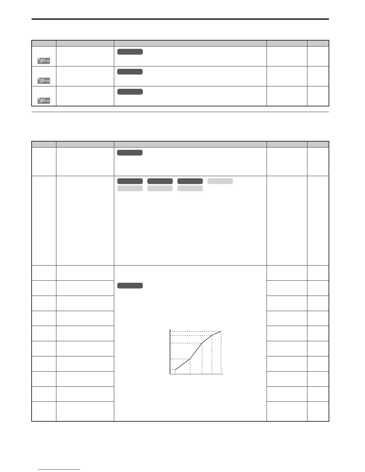
E1-04
(303H)
Maximum Output Frequency
These parameters are only applicable when E1-03 is set to F.
To set linear V/f characteristics, set the same values for E1-07 and E1-09. In this case, the
setting for E1-08 will be disregarded. Ensure that the four frequencies are set according to these
rules:
E1-09 ≤ E1-07 < E1-06 ≤ Ε1−11 ≤ E1-04
Note that if E1-11 = 0, then both E1-11 and E1-12 are disabled, and the above conditions do not
apply.
Note: Some parameters may not be available depending on the control mode.
• E1-07, E1-08 and E-10 are available only in the following control modes: V/f Control, V/f
with PG, Open Loop Vector.
• E1-11, E1-12 and E-13 are available only in the following control modes: V/f Control, V/f
with PG, Open Loop Vector, Closed Loop Vector.
Default:
<4> <14>
Min: 40.0
Max: 400.0
<29>
197
E1-05
(304H)
Maximum Voltage
Default:
<4> <14> <18>
Min: 0.00 V
Max: 255.0 V
<18>
197
E1-06
(305H)
Base Frequency
Default:
<4> <14>
Min: 0.0
Max: E1-04
<29>
197
E1-07
(306H)
Middle Output Frequency
Default:
<4>
Min: 0.0
Max: E1-04
197
E1-08
(307H)
Middle Output Frequency Voltage
Default:
<4> <18>
Min: 0.0 V
Max: 255.0 V
<18>
197
E1-09
(308H)
Minimum Output Frequency
Default:
<4> <14>
Min: 0.0
Max: E1-04
<26> <29>
197
E1-10
(309H)
Minimum Output Frequency
Voltage
Default:
<4> <18>
Min: 0.0 V
Max: 255.0 V
<18>
197
E1-11
(30AH)
<21>
Middle Output Frequency 2
Default: 0.0 Hz
Min: 0.0
Max: E1-04
<26>
197
E1-12
(30BH)
<21>
Middle Output Frequency Voltage
2
Default: 0.0 V
Min: 0.0 V
Max: 255.0 V
<18>
197
E1-13
(30CH)
Base Voltage
Default: 0.0 V
<18> <27>
Min: 0.0 V
Max: 255.0 V
<18>
197
All Modes

 Loading...


