5.7 H: Terminal Functions
224 YASKAWA ELECTRIC SIEP C710616 27C YASKAWA AC Drive A1000 Technical Manual
Setting 7A, 7B: KEB Ride-Thru 2 (N.C., N.O.)
An input terminal set to 7A or 7B can trigger Single Drive KEB Ride-Thru during deceleration. If enabled, L2-29 is
disregarded. Refer to KEB Ride-Thru Function on page 249 for details.
Note: KEB Ride-Thru 1 and 2 cannot both be assigned to the input terminals at the same time. Doing so will trigger an oPE3 error.
Setting 7C, 7D: Short Circuit Braking (N.O., N.C.) (OLV/PM, AOLV/PM)
An input programmed for this function can be used to activate Short Circuit Braking in Open Loop Vector control modes
for PM motors. By linking all three phases of a PM motor, Short Circuit Braking creates a braking torque that can be used
to stop a rotating motor or prevent a motor from coasting due to external forces (such as the windmill effect in fan
applications). Parameter b2-18 can be used to limit the current during Short Circuit Braking.
Setting 7E: Forward/reverse detection (for V/f Control with Simple PG Feedback)
When a digital input is programmed for this function, the input determines the motor rotation direction for V/f Control
with Simple PG feedback (A1-02 = 0 and H6-01 = 3). If the input is open, the speed feedback signal is considered to be
forward. If the input is closed, it is considered to be in reverse. Refer to H6: Pulse Train Input/Output on page 241.
Setting 7F: Bi-Directional PID Output Selection
If PID output to bi-directional output conversion is enabled in parameter d4-11, a digital input programmed for 7F can be
used to switch between normal output or bi-directional output. If the digital input is open, the PID output builds the out-
put frequency reference.
If the input is closed, the PID output is converted to bi-directional output frequency reference. Refer to d4-11: Bi-
Directional Output Selection on page 187.
Setting 90 to 97: DriveWorksEZ Digital Input 1 to 8
These settings are for digital inputs functions used in DriveWorksEZ. Normally there is no need to change these settings.
Setting 9F: DriveWorksEZ Disable
This function is used to enable or disable a DriveWorksEZ program in the drive. An input programmed for this function
is effective only if A1-07 = 2.
◆ H2: Multi-Function Digital Outputs
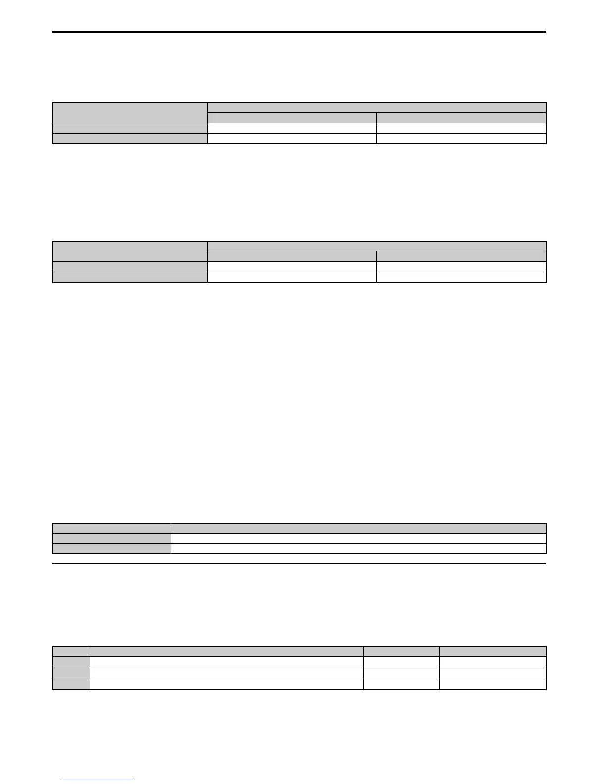
■ H2-01 to H2-03: Terminal M1-M2, M3-M4, and M5-M6 Function Selection
The drive has three multi-function output terminals. Table 5 .38 lists the functions available for theses terminals using
H2-01, H2-02, and H2-03.
Digital Input Function
Drive Operation
Input Open Input Closed
Setting 7A (N.C.) Single Drive KEB Ride-Thru 2 Normal operation
Setting 7B (N.O.) Normal operation Single Drive KEB Ride-Thru 2
DIgital Input Function
Drive Operation
Input Open Input Closed
Setting 7C (N.O.) Normal operation Short Circuit Braking
Setting 7D (N.C.) Short-Circuit Braking Normal operation
Status Description
Open DriveWorksEZ enabled
Closed DriveWorksEZ disabled
No. Parameter Name Setting Range Default
H2-01
Terminal M1-M2 Function Selection
0 to 192 0: During run
H2-02
Terminal M3-M4 Function Selection
0 to 192 1: Zero Speed
H2-03
Terminal M5-M6 Function Selection
0 to 192 2: Speed agree 1

 Loading...


