4.6 Application Selection
106 YASKAWA ELECTRIC SIEP C710616 27C YASKAWA AC Drive A1000 Technical Manual
◆ Notes on Controlling the Brake when Using the Hoist Application Preset
■ Prevent accidental Brake Release during Baseblock
The hoist application selection uses the frequency detection function for controlling the brake.
Although the drive output will be shut off, the drive still maintains the frequency reference if the Run command remains
active when an external Baseblock command is given (H1- = 8 or 9). Disable the frequency detection during
baseblock by setting parameter L4-07 = 0 to prevent the brake remaining open while the drive is in baseblock.
■
Controlling the Brake in Closed Loop Vector Control
For hoist applications using Closed Loop Vector Control, Yaskawa recommends setting the “During frequency output”
signal to a digital output (H2-01 = 37 for terminal M1-M2) in order to control the brake. This way, the brake will always
close during baseblock, and the setting of parameter L4-07 as described above will not affect brake control.
■
Brake Control During Safe Disable Input
If the Safe Disable input is triggered, the drive output will shut off and the frequency reference will reset to 0. The brake
will also close, regardless if the Run command is active. The Run command must be cycled before the drive can restart.
■
Related Parameter Settings
The table below shows the parameter settings needed when using output terminals M1-M2 as brake control output.
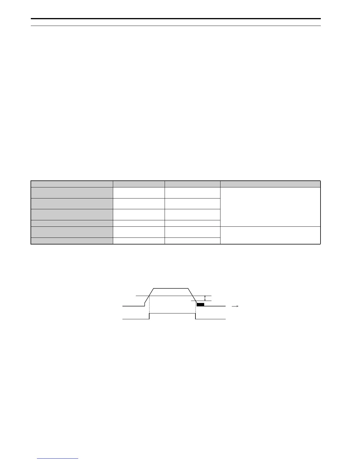
Figure 4.11
Figure 4.12 Frequency Detection 2
Function
<1> This is the setting recommended when using Open Loop Vector Control. If using V/f Control, set the level as the motor rated slip frequency
plus 0.5 Hz. Not enough motor torque will be created if this value is set too low, and the load may tend to slip. Make sure this value is greater
than the minimum output frequency and greater than the value of L4-02, as shown in the diagram below. If set too high, however, there may be
a jolt at start.
<2> Hysteresis for Frequency detection 2 can be adjusted by the Frequency detection width (L4-02) between 0.0 and 0.5 Hz. If the load slips during
stop, make changes in steps of 0.1 Hz until the load no longer slips.
Parameter Setting Comment
Frequency Detection 2 Digital Output
(for brake control)
H2-01 5
Use this setup for V/f control modes or Open Loop
Vector control
Speed Agreement Detection Level
(frequency for the brake to open)
L4-01 1.0 to 3.0 Hz
<1>
Speed Agreement Width
(bandwidth for the brake to close)
L4-02 0.0 to 0.5 Hz
<2>
Frequency Detection during Baseblock L4-07 0
DC Injection Braking Start Frequency
(frequency for the brake to close)
b2-01 0.1 to 0.5 Hz
Use this setup in Closed Loop Vector control for IM or
PM motors
During Frequency Output H2-01 37

 Loading...


