7.3 Periodic Maintenance
The drive has Maintenance Monitors that keep track of component wear. This feature provides advance maintenance
warning and eliminates the need to shut down the entire system for unexpected problems. The drive allows the user to
check predicted maintenance periods for the components listed below.
• Cooling Fan, Circulation Fan, Control Board Cooling Fan
• Electrolytic Capacitors
• Inrush Prevention Circuit
•IGBTs
For replacement parts, contact the distributor where the drive was purchased or contact Yaskawa directly.
◆ Replacement Parts
Table 7.3 contains the estimated performance life of components that require replacement during the life of the drive.
Only use Yaskawa replacement parts for the appropriate drive model and revision.
Table 7.3 Estimated Performance Life
NOTICE: Estimated performance life based on specific usage conditions. These conditions are provided for the purpose of replacing
parts to maintain performance. Some parts may require more frequent replacement due to poor environments or rigorous use. Usage
conditions for estimated performance life:
• Ambient temperature: Yearly average of 40°C (IP00 enclosure)
• Load factor: 80% maximum
• Operation time: 24 hours a day
■ Performance Life Monitors Maintenance Monitors
The drive calculates the maintenance period for components that may require replacement during the life of the drive. A
percentage of the maintenance period is displayed on the digital operator by viewing the appropriate monitor parameter.
When the maintenance period reaches 100%, there is increased risk that the drive may malfunction. Yaskawa
recommends checking the maintenance period regularly to ensure maximum performance life.
Refer to Recommended Periodic Inspection on page 348 for more details.
Table 7.4 Performance Life Monitors Used for Component Replacement
■ Alarm Outputs for Maintenance Monitors
An output can be set up to inform the user when a specific components has neared its expected performance life.
When one of multi-function digital output terminals has been assigned the maintenance monitor function (H2- = 2F),
the terminal will close when the cooling fan, DC bus capacitors, or DC bus pre-charge relay reach 90% of the expected
performance life, or the IGBTs have reached 50% of their expect performance life. Additionally the digital operator will
display an alarm like shown in Table 7.5 to indicate the specific components that may need maintenance.
Table 7.5 Maintenance Alarms
Component Estimated Performance Life
Cooling Fan, Circulation Fan 10 years
Electrolytic Capacitors 10 years
<1>
<1> The drive has few serviceable parts and may require complete drive replacement.
Parameter Component Contents
U4-03
Cooling Fan, Circulation Fan,
Control Board Cooling Fan
Displays the accumulated operation time of the fan, from 0 to 99999 hours. This value is automatically reset to 0 once it
reaches 99999.
U4-04 Displays the accumulated fan operation time as a percentage of the specified maintenance period.
U4-05 DC Bus Capacitors Displays the accumulated time the capacitors are used as a percentage of the specified maintenance period.
U4-06 Inrush (pre-charge) Relay Displays the number of times the drive is powered up as a percentage of the performance life of the inrush circuit.
U4-07 IGBT Displays the percentage of the maintenance period reached by the IGBTs.
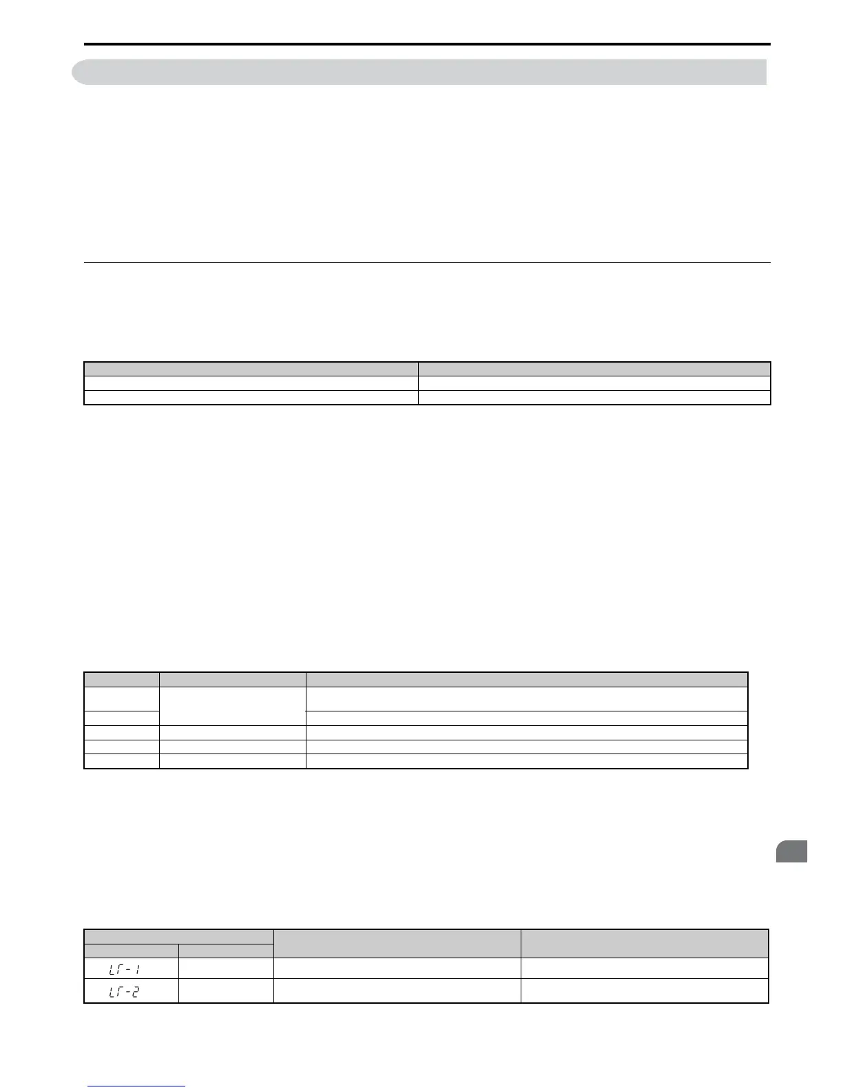
Alarm Display
Function Corrective Action
LED Operator LCD Operator
<1>
LT-1 The cooling fans have reached 90% of their designated life time. Replace the cooling fan.
<1>
LT-2
The DC bus capacitors have reached 90% of their designated life
time.
Replace the drive.

 Loading...


