5.8 L: Protection Functions
262 YASKAWA ELECTRIC SIEP C710616 27C YASKAWA AC Drive A1000 Technical Manual
Automatic Parameter Setup
In Closed Loop Vector Control for induction motors or PM motors the Inertia Auto-Tuning function can be used to let the
drive automatically adjust this parameter. Refer to Auto-Tuning on page 109.
Manual Parameter Setup
Parameter L3-25 can be calculated by:
■
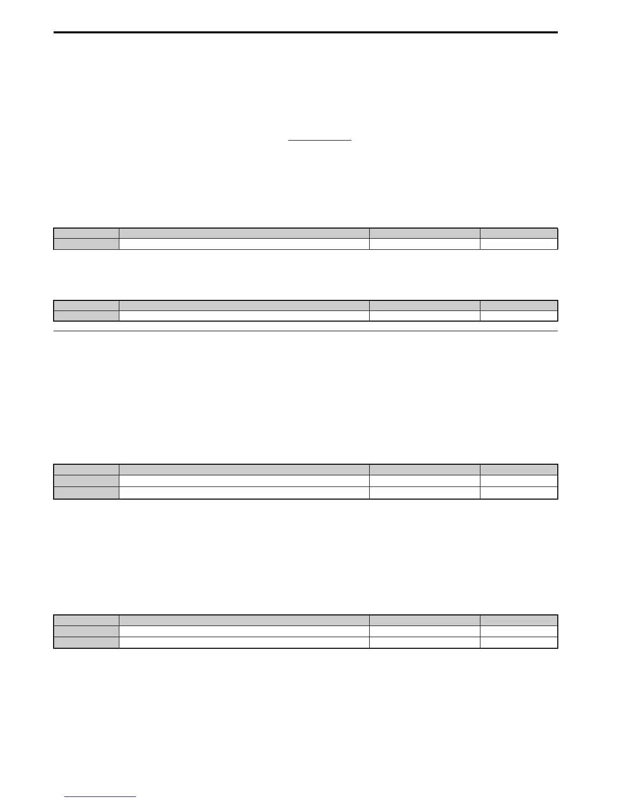
L3-26: Additional DC Bus Capacitors
Sets the capacity of any additional DC bus capacitors that have been installed. This data is used in calculations for Single
Drive KEB Ride-Thru 2. This setting needs to be adjusted only if external capacity is connected to the drives DC bus and
Single Drive KEB 2 is used.
■
L3-27: Stall Prevention Detection Time
Sets a delay time from when the Stall Prevention level is reached and the actual Stall Prevention function is activated.
◆ L4: Speed Detection
These parameters set up the speed agree and speed detection functions which can be assigned to the multi-function
output terminals.
■
L4-01, L4-02: Speed Agreement Detection Level and Detection Width
Parameter L4-01 sets the detection level for the digital output functions “Speed agree 1,” “User-set speed agree 1,”
“Frequency detection 1,” and “Frequency detection 2.”
Parameter L4-02 sets the hysteresis level for these functions.
Refer to H2-01 to H2-03: Terminal M1-M2, M3-M4, and M5-M6 Function Selection on page 224, Settings 2, 3, 4, and
5.
■
L4-03, L4-04: Speed Agreement Detection Level and Detection Width (+/-)
Parameter L4-03 sets the detection level for the digital output functions “Speed agree 2,” “User-set speed agree 2,”
“Frequency detection 3,” and “Frequency detection 4.”
Parameter L4-04 sets the hysteresis level for these functions.
Refer to H2-01 to H2-03: Terminal M1-M2, M3-M4, and M5-M6 Function Selection on page 224, Settings 13, 14, 15,
and 16.
■
L4-05: Frequency Reference Loss Detection Selection
The drive can detect a loss of an analog frequency reference from input A1, A2, or A3. Frequency reference loss is
detected when the frequency reference drops below 10% of the reference before or below 5% of the maximum output
frequency within 400 ms.
No. Name Setting Range Default
L3-26 Additional DC Bus Capacitors 0 to 65000 μF
0 μ
F
No. Name Setting Range Default
L3-27 Stall Prevention Detection Time 0 to 5000 ms 50 ms
No. Name Setting Range Default
L4-01
Speed Agreement Detection Level
0.0 to 400.0 Hz 0.0 Hz
L4-02
Speed Agreement Detection Width
0.0 to 20.0 Hz Determined by A1-02
No. Name Setting Range Default
L4-03
Speed Agreement Detection Level (+/-)
-400.0 to 400.0 Hz 0.0 Hz
L4-04
Speed Agreement Detection Width (+/-)
0.0 to 20.0 Hz Determined by A1-02

 Loading...


