Figure 8.8
Figure 8.8 Connecting a Braking Unit (CDBR type) and Braking Resistor Unit (LKEB type)
(CIMR-A2A0169 to 0415, 4A0088 to 0675)
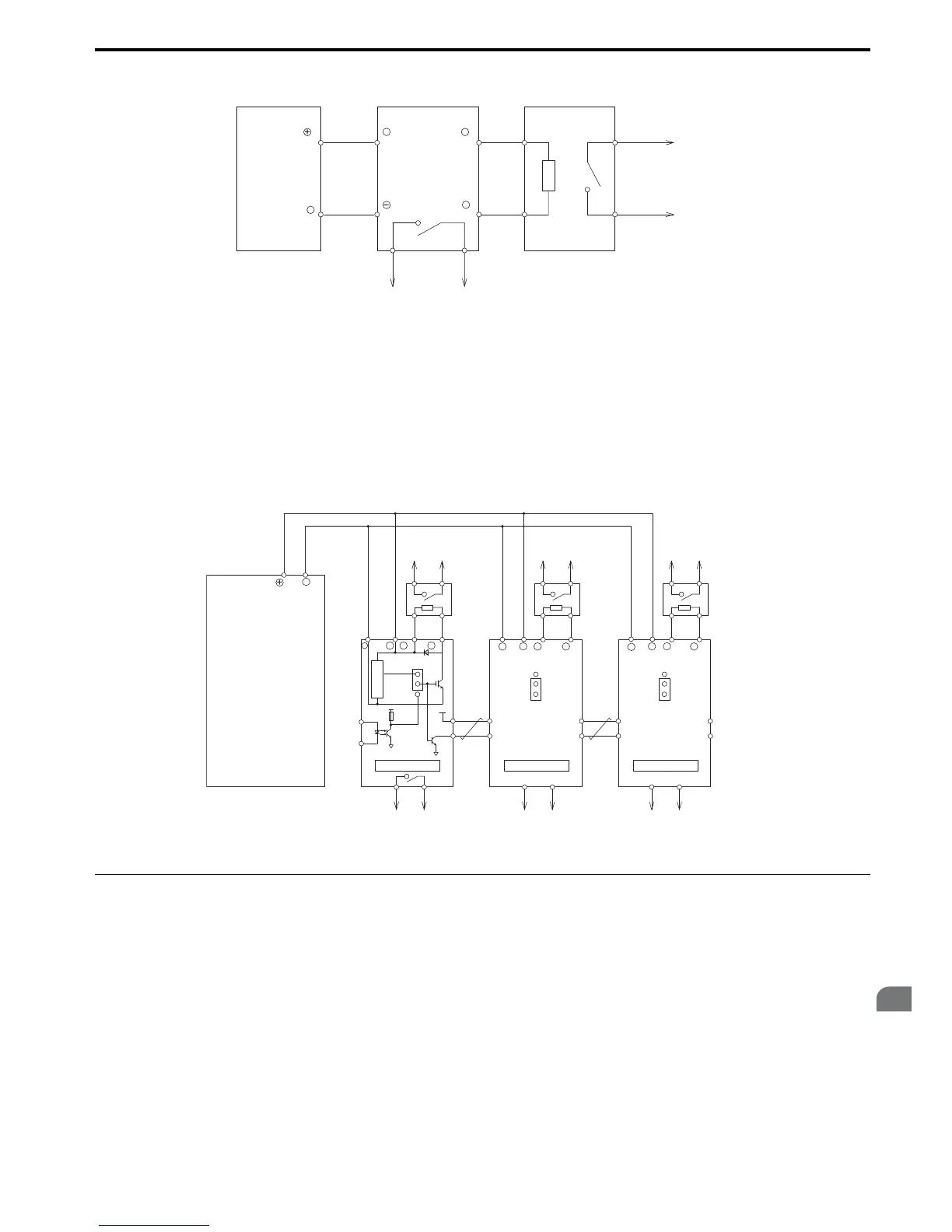
■ Using Braking Units in Parallel
When multiple braking units are used, they must be installed with a master-slave configuration with a single braking unit
acting as the master. Figure 8.9 illustrates how to wire braking units in parallel.
Wire the thermal overload contacts relays of all CDBRs and all braking resistors in series, then connect this signal to a
drive digital input. This input can be used to trigger a fault in the drive in case of overload in any of the CDBRs or
braking resistors.
Figure 8.9
Figure 8.9 Connecting Braking Units in Parallel
◆ Installing a Molded Case Circuit Breaker (MCCB)
Install a MCCB for line protection between the power supply and the main circuit power supply input terminals R/L1, S/
L2, and T/L3. This protects the main circuit and devices wired to the main circuit while also providing overload
protection.
Consider the following when selecting and installing a MCCB:
• The capacity of the MCCB should be 1.5 to 2 times the rated output current of the drive. Use a MCCB with an
operation characteristics so that the MCCB does not trip faster than the drive overload protection works (shuts off the
drive after 1 min. operation at 150% of the drive rated current).
• If several drives are connected to one MCCB, use a sequence that shuts the power OFF when an error occurs in one
drive by using magnetic contactor (MC) as shown in the following figure.
Thermal Relay
Trip Contact
Drive
Braking Unit
(CDBR type)
Braking Resistor Unit
(LKEB type)
Thermal Overload
Protector Trip Contact
1
2
P
34
3 + + 0
−− 0
B
+
−
Drive
Braking Resistor
Overheat Contact
(Thermal Relay Trip Contact)
Braking Resistor
Overheat Contact
(Thermal Relay Trip Contact)
Braking Resistor
Overheat Contact
(Thermal Relay Trip Contact)
Braking
Resistor
Unit
Braking
Resistor
Unit
Braking
Resistor
Unit
Braking Unit 2
+15
5
1
2
6
SLAVE
MASTER
Level Detector
Cooling Fin Overheat Contact
(Thermoswitch Contact)
Cooling Fin Overheat Contact
(Thermoswitch Contact)
Cooling Fin Overheat Contact
(Thermoswitch Contact)
Braking Unit 3
Braking Unit 1
1
34
34 3
5
6
5
6
1
2
4
2
3
1
P
2
B
−
− 0+ 0+
−
+−+− + 0 − 0+ 0 − 0
BPBP
12 1 2
MASTER
SLAVE
MASTER
SLAVE
+

 Loading...


